Table of Contents
Advertisement
Quick Links
Advertisement
Table of Contents

Related Manuals for C-Tech HTHY-8159


Summary of Contents for C-Tech HTHY-8159
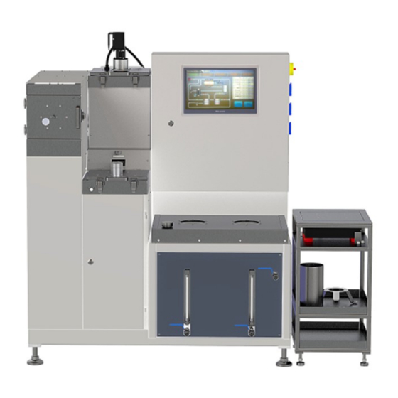
- Page 1 ASPHALT MIX ANALYZER HTHY-8159/8159A...
-
Page 2: Table Of Contents
CONTENTS Preface ................................1 Technical specifications and installation ......................4 III. Equipment introduction ..........................6 IV. Operation ..............................12 Operation interface instructions ......................... 21 VI. Maintenance ..............................26 VII. Balance calibration method ........................26 Recirculating chiller DL-400 instruction manual ................... 29 Circulating water vacuum pump SHB-III series instruction manual .............. 43 Rotary evaporator R-3001 instruction manual ..................... -
Page 3: Preface
I. Preface Safety tips Notice for use When using the equipment under different circumstances, the manufacturer does not assume any responsibility for any foreseeable harm caused directly or indirectly to people, things or animals. Without prior notice, the manufacturer has the right to make changes to the file information or equipment. - Page 4 During operation, check the condition of the equipment. If it is in a dangerous situation, stop working immediately and consult the manufacturer's after-sales service department. It is the customer's responsibility to verify whether the installation or use is carried out according to the instructions. Please contact the manufacturer when in doubt.
- Page 5 things or people due to improper use, error and negligence, but does not assume all responsibilities. Warning and danger signs This equipment is designed and manufactured in accordance with the current standards, so it is equipped with well-designed mechanical and electrical safety devices to protect the operator or user from possible injury.
-
Page 6: Technical Specifications And Installation
The manufacturer can provide further information. II. Technical specifications and installation Technical specifications Model HTHY-8159A HTHY-8159 Conventional Asphalt Mixture 3.5Kg Conventional Asphalt Mixture 3.5Kg Maximum sample weight Rubber Asphalt Mixture 1.5Kg Centrifuge speed... - Page 7 pipe on the back of the equipment upwards and outwards to the ventilation duct opening. Power connection Power requirements: 380V three-phase four-wire system with working zero line. Connection of cooling water pipes Chiller water pipe interface Analyzer water pipe interface Figure 1 As shown in Figure 1, the chiller’s inlet is connected to the outlet of the analyzer, and the chiller’s outlet is connected to the water inlet of the analyzer.
-
Page 8: Equipment Introduction
Equipment transport and movement must be entrusted to qualified personnel who can ensure proper movement. III. Equipment introduction Structure Power supply Rubber asphalt mixture Conventional asphalt washing chamber mixture washing chamber Electric cabinet Weighing device Centrifuge Solvent tank Mixture liquid tank Figure 2 - 6 -... - Page 9 Working principle Figure 3 1- Washing chamber 2- Washing heater 3- Mixture liquid window 4- Centrifuge 5- Centrifuge motor 6-Condenser 7-Vacuum pump 8-Drain valve 9-Solvent pump 10-Cooling device 11-Solvent tank 12-Heater 13-Mixture liquid tank 14-Rubber washing chamber The working principle of the device is shown in Figure 3. Put the dried and dispersed asphalt mixture (conventional asphalt mixture does not exceed 3.5Kg, rubber asphalt mixture does not exceed 1.5Kg) into the corresponding washing drum.
- Page 10 As shown in Figure 4, the washing chamber is made of stainless steel. In order to improve the washing efficiency, the washing drum is driven by the motor to rotate in the washing chamber, and is equipped with an ultrasonic washing device. The washing chamber is equipped with a safety lock, and the equipment cannot be started when the cover of the washing chamber is open.
- Page 11 Rubber asphalt mixture washing device, as shown in Figure 6. Washing motor Handle Cover Hasp lock Rubber asphalt washing chamber Figure 6 The rubber-asphalt mixture washing bucket, as shown in Figure 7, is made of stainless steel. There are three specifications of 63μm, 75μm and 90μm, and the appropriate size can be selected according to the actual use.
- Page 12 Figure 10 Figure 9 Centrifuge device The centrifuge device (shown in Figure 11) is mainly Mixture composed of a centrifuge chamber, a centrifuge motor, liquid a centrifuge cup (shown in Figure 13), a movable cover window plate and a safety lock, as shown in Figure 12. It is mainly used to separate the mineral powder from the mixture liquid discharged from the washing drum.
- Page 13 Distillation system The distillation system (shown in Figure 14) mainly includes a solvent tank (left side), a mixture liquid tank (right side), cooling pipe, and heater. There are two heating tubes in the mixture liquid tank for heating, and the cooling pipe is located above the solvent tank. The dispensing valve is used to take a sample of the asphalt mixture liquid directly from the centrifuge.
-
Page 14: Operation
device needs to be installed on a flat floor, away from vibration sources. There is a shelf under the weighing device, and the accessories related to the test can be placed on the shelf, which is convenient for use in the test. Weighing Platform Shelf... - Page 15 Testing method for conventional asphalt mixture ①. Turn on the power of the device. ②. On the startup interface (as shown in Figure 16), click the "Standard Wash" button. Figure 16 ③. Click the "Balance" tab and click the "Balance zero" button. Weigh the washing drum, and click Washing Drum (g)", as shown in Figure 17;...
- Page 16 Figure 18 WARNING! The maximum amount of mixture that can be added to the washing drum is no more than 3.5Kg, and it is also determined by the mineral powder content in the mixture, which cannot exceed the maximum mineral powder capacity of the centrifuge cup! ⑤.
- Page 17 Note: When placing the filter paper, the smooth surface should be in contact with the inner wall of the centrifuge cup. ⑦. Make sure that the doors of the washing chamber, rubber asphalt chamber and centrifuge chamber are closed. Figure 20 ⑧.
- Page 18 ⑪. On the " Standard Wash " interface, click the "Start" button, as shown in Figure 22, the test starts. Note: When the set washing times are reached, observe the color of the mixture liquid flowing out of the washing chamber through the mixture window located on the centrifuge movable cover. If the color of the liquid is not colorless and transparent, adjust the washing cycles, and click "Plan Save"...
- Page 19 ⑬. Pour out the aggregate in the washing drum and the mineral powder in the centrifuge cup, and Figure 23 clean the washing drum and the centrifuge cup. ⑭. After the test is completed, close the washing chamber cover and the centrifuge movable cover. ⑮.
- Page 20 Figure 25 Figure 26 WARNING! The maximum amount of mixture that can be added to the rubber washing drum is no more than 1.5Kg, and it is also determined by the mineral powder content in the mixture, which cannot exceed the maximum mineral powder capacity of the centrifuge cup! ⑤.
- Page 21 of the centrifuge cup. Figure 28 Figure 27 ⑦. Make sure that the doors of the washing chamber, rubber asphalt chamber and centrifuge chamber are closed. ⑧. Check whether the pipeline from the chiller to the solvent tank cooling coil is firmly connected. If you use water cooling, you need to check that the water inlet of the device is connected to the tap water outlet, and the water outlet of the device is connected to the drain.
- Page 22 Figure 29 ⑬. Open the centrifuge cover to remove the centrifuge cup, weigh it, and enter it into the system. Figure 30 ⑭. Click the "Calculate Results" button to calculate the test results, and you can also choose whether to print the test results as needed. ⑮.
-
Page 23: Operation Interface Instructions
⑱. Perform routine maintenance on equipment. Handling method of abnormal interruption The steps in progress when Situation Solution abnormally interrupted The test can be restarted without Centrifuge starts The centrifuge did not start properly. changing the sample. The test can be restarted without Mixture soaking Liquid only in the washing drum. - Page 24 After turning on the power, automatically enter the main interface. Choose the washing process as needed ("Standard Wash" or "Rubber Wash") (shown in Figure 31); Figure 31 Conventional asphalt mixture washing Real-time display of the temperature, liquid level, start and stop of each component, and the currently washing step (as shown in Figure 32);...
- Page 25 Set time: It means the time required for each step, can be changed at the "Washing Plan" interface. Washing plan According to the amount of mixed material and the content of mineral powder to set different parameters. Multiple washing plans can be saved according to different mixtures (Figure 33); Test process Test time setting Interface selection...
- Page 26 Centrifuge stop: The time required for the centrifuge to drop from the highest speed to 0, it is recommended not to be less than 1 minute; Distilling: The time for distilling the solvent of the mixture liquid tank to a low liquid level; Stop: The overall test delay stop time.
- Page 27 S-chamber heating: Heating the washing chamber (or R rubber asphalt washing chamber) to control the temperature; Centrifuge heat: Heating and temperature control of centrifuge chamber; S-chamber empty: Drain the mixture liquid in the washing chamber (or R rubber asphalt washing chamber) into the centrifuge cup (the centrifuge must be started in advance);...
-
Page 28: Maintenance
Centrifuge cup + filler (g): After the test, there may be some mineral powder in the washing chamber, which needs to be cleaned and weighed together in the centrifuge cup; Washing drum (g): When weighing the washing drum, be sure to clean it up in advance. VI. - Page 29 Make a transfer cable as shown Cross welding of wire2 and wire 3 DB9 male connector DB9 female connector The computer communicates with the balance 1. Computer management 2. Device manager 3. USB Serial Port (COM3) Open software calibration - 27 -...
- Page 30 clear calibration Open ① clear calibration clear calibration After the calibration was completed, repeat testing the result of weighing with the weights (It is best to make the weight stay in quiescence for 10 seconds after placing it on) - 28 -...
-
Page 31: Recirculating Chiller Dl-400 Instruction Manual
RECIRCULATING CHILLER DL-400 INSTRUCTION MANUAL I. Product Overview 1. Preface Thank you for using "DL-400 Recirculating Chiller". This instruction manual describes the installation, use, and maintenance of the recirculating chiller. Before using this device, please be sure to read the instruction manual carefully. 2. - Page 32 Any operation not in accordance with the instruction manual is improper use. Any damage caused by improper use shall be borne by the user. Use is prohibited under the following conditions: a) Explosive gas atmosphere or explosive dust atmosphere; b) Places where the power supply does not meet the requirements; c) Strong magnetic field environment, corrosive environment.
- Page 33 Forbidden Do not use in outdoor environments. Rain, splashing water, etc. will cause the shell to be electrified, causing casualties Warning Be sure to connect the power supply specified on the equipment nameplate; Please implement equipotential connection and ground the equipment reliably; ...
- Page 34 2.6 Other hazards Warning When there are corrosive substances such as acid and alkali vapor around the equipment, the performance and service life of the components will be affected. Do not use the refrigerant used in contact with food, medicine, tobacco, etc., to avoid personal injury 2.7 Security measures When operating this equipment, please wear personal protective equipment, such as...
- Page 35 5. Control Panel Upper limit temperature indicator light Lower limit temperature indicator light Cooling working indicator light Cooling enable light Power Indicator Cycle light Power switch Cooling switch Cycle switch 10. Settings key 11. Down key 12. Up key 13. Temperature display II.
- Page 36 5) Connect hoses to the liquid outlet and liquid return ports of the equipment, and connect to the equipment that needs to be cooled. 3001 6) If liquid is splashed or spilled on the equipment casing, it should be wiped clean first, and all components can be put into use after confirming that they are in good condition.
- Page 37 Output cooling capacity at 0℃(W) Refrigerant R134a Total power(W) Power(W) Circulation Flow rate(L/min) pump Pressure(bar) Secondary refrigerant outlet and return port PP tube: Φ10×1.5mm Connection hose Silicone rubber hose: Φ13×Φ9mm Liquid storage tank material 304 stainless steel Dimensions (mm)(W×D×H) 245×430×550 Net weight (kg) * The operating temperature range should be ≤...
- Page 38 WARNING! Ethanol is flammable, pay attention to fire prevention and ventilation! 3) Ethanol explosion limit: 3.5% to 18.0% (volume); open flash point: 13°C. 4) Users can choose the appropriate secondary refrigerant according to their needs. 5) It is strictly forbidden to use brine (KCl/H2O, NaCl/H2O, CaCl2/H2O) as a secondary refrigerant.
- Page 39 Click " ", the indicator lights are on, and the temperature displays " " 4S (as shown in figure below), and enters the standby state, displaying the current temperature of the secondary refrigerant (as shown in figure below). Temperature setting 1) Press the “...
- Page 40 controller will automatically save the setpoints. If the " " key is not pressed for a long time, the controller will abandon the setting, keep the original setting value, and exit the setting state. 5. Starting the circulation system On the premise of ensuring the smooth flow of the circulation system, click the " "...
- Page 41 be released from the liquid outlet in time to prevent the secondary refrigerant from flowing backwards. V. Protection functions 1) The compressor itself is equipped with an overheat protector, and its main circuit is equipped with a fuse. When the temperature of the compressor is too high or the current is too high, it will automatically cut off the power supply for protection.
- Page 42 specifications if they are found to be aged or damaged. 2. Maintenance of cooling system In order to maintain the cooling effect, please clean the cooling system (condenser) regularly, the steps are as follows: 1) Turn off the power of the device. 2) Use a + screwdriver to remove the two screws at the bottom of the front ventilation panel, and pull down to remove the front ventilation panel.
- Page 43 3. Common faults and troubleshooting Faults Reasons Troubleshooting Power is not connected Check the power line Turn on the power switch. All indicators are off Fuse is broken Replace the fuse of the same type Poor sensor contact Please stop using it and contact our Display "-EO-"...
- Page 44 Fan not started outlet Please stop using it and contact our exhaust air or abnormal The fan is stuck company or contact professional fan is on air volume maintenance personnel Fan blade deformation - 42 -...
-
Page 45: Circulating Water Vacuum Pump Shb-Iii Series Instruction Manual
CIRCULATING WATER VACUUM PUMP SHB-III SERIES INSTRUCTION MANUAL I. Overview The circulating water vacuum pump is a vacuum pump that uses circulating water as the working fluid and uses the fluid jet to generate negative pressure for ejection. This is an efficient circulating water vacuum pump used to provide vacuum conditions for the process of evaporation, distillation, crystallization, drying, sublimation, filtration, decompression, degassing, etc. - Page 46 SHB-IIIA: Ejector and suction nozzle are made of stainless steel (ANSI standard), others are the same as SHB-III. SHB-IIIS: The pump body is made of PP material, which is more suitable for acid gas, and the others are the same as SHB-III. ...
- Page 47 tank clean. 2. Vacuum operation. Connect the suction sleeve of the equipment that needs to be vacuumed tightly to the suction nozzle of the machine. Turn off the cycle switch and turn on the power switch to start vacuuming. The vacuum degree can be observed through the vacuum gauge corresponding to the suction nozzle.
- Page 48 Faults Reasons Troubleshooting 1. Low motor speed or low voltage Check whether the voltage is stable 2. Vacuum bottle and check valve are Clean up the internal dirt or replace with a clogged or corroded by dirt new bottle and valve core 3.
- Page 49 VI. Vacuum performance under different temperature conditions Temperature ℃ ~0.099 ~0.099 ~0.099 ~0.099 Vacuum degree MPa 0.097 0.096 0.095 ~750 ~750 ~748 ~746 mmHg This series of vacuum pumps has the characteristics of high ultimate vacuum and fast pumping speed. The pumping speed of the new vacuum bottle after transformation is increased by ~30% on the original basis.
-
Page 50: Rotary Evaporator R-3001 Instruction Manual
ROTARY EVAPORATOR R-3001 INSTRUCTION MANUAL I. Safety This chapter describes the safety rules/regulations involved in the installation and use of "R3001 rotary evaporator". Users should grasp the relevant warning signs, strictly abide by the operation procedures, to ensure product and personal safety, to avoid accidents. The warning marks used in the instruction manual All warning signs need extra attention Danger... - Page 51 Danger Do not use in the environment of explosive gas or explosive dust. Do not use the hazardous materials that beyond the design scope Non-professional personnel are forbidden to carry out maintenance Warning Be sure to connect the power supply specified on the product nameplate; ...
- Page 52 Warning The specimen added to the product or the solvents used near the product may form peroxides, flammable solvents in high concentrations. Beware of explosions when handling with dangerous materials or unknown components of the specimen. Safety precautions When operating the product, please wear personal protective equipment (protective glasses, gloves and labor suits etc.
- Page 53 Improper use All the operations which are not in accordance with the relevant specifications in the product manual belong to the improper use. The damage caused by the improper use shall be borne by the user. Do not use under the following conditions: ...
- Page 54 Diameter of condenser nozzle (mm) ф10 Machine base (mm) T Type Movements itinerary (mm) Rotating speed adjustment mode Knob Adjustment Speed display mode Lifting mode Electric Protection function Overload protection, Short circuit protection, Ground fault protection Power supply 100-240V, 50/60Hz The fuse F2AL, 250V Ambient temperature...
- Page 55 Temperature sensor Pt100 Bath material SUS 304 Specification Bath size (mm) ф254x130 Bath volume(L) Power supply 220-240V~, 50/60Hz 110V~, 60Hz The fuse F8AL, 250V Fl5AL, 250V Ambient temperature 5~35 (℃) Environmental relative humidity (%) ≦65 Shell protection class IP20 Pollution prevention level Level 2 Overall dimensions WxDxH (mm) 290x270x246...
- Page 56 Figure 1 Components of Rotary Evaporator Components item of the product are shown in table 3. Table 3 Components and quantity of the rotary evaporator Picture Item Quantity Glass feeding valve 1 piece Glass condenser 1 piece Collecting bottle clamp 1 piece Collecting bottle 1 piece...
- Page 57 0.5L (1 piece) Rotary bottle 1L (1 piece) Condenser pole 1 piece Feeding valve connecting hose 1 piece Host 1 set Bath 1 piece 1- The circulation fluid interface 2- The 50 # Flange 3- Interface of collecting bottles 4- The circulation fluid interface 2 5- The feeding port 6-Bleeder Figure 2 Interface of glass condenser 1- The lock knob...
- Page 58 1- Rotating Speed display window 2-The rotating speed regulator Figure 4. The control panel 1- The up button 2- The down button Figure 5 Up and down control panel Bath configuration 1-The temperature setting 2-Temperature display window 3-The set value decreases 4-The set value increases Figure 6a Figure 6b...
- Page 59 IV. Unpacking and installation Unpacking and installation 1) Glass is fragile, please unpack with caution. 2) Small parts easy to be lost, please keep properly. 3) Put the product on the level and stable platform, and consider its maximum size. 4) Before installation, please compare with the packing list and check that whether the equipped components are complete.
- Page 60 Figure 8 As shown in figure 9, assemble the rotatory bottle withdrawing coupler (11), then install the rotary bottle withdrawing coupler (11) on one side of the glass rotating axis; press and hold the lock button of rotating axis , turn the rotating axis to the locking position, maintain the rotating axis position, and tighten the bottle withdrawing coupler (11) clockwise.
- Page 61 Figure 10 The auxiliary vacuum sealing ring (7) will be stacked on the main vacuum sealing ring (8), the convex side of the auxiliary vacuum sealing ring (7) should be exposed, as shown in figure 11. Figure 11 Put the condenser locking nut (5) to 50 # flange of the glass condenser (2) , as shown in figure - 59 -...
- Page 62 Figure 12 The locking spring of condenser (6) will be installed on the locking nut (5), nudging locking spring (6) to the 50 # flange of the glass condenser, as shown in figure 13. Figure 13 Install the glass condenser which is equipped with the condenser locking nut (5) and the locking spring (6) on the left side of the rotating axis.
- Page 63 Figure 15 Adjust the position of shroud ring of the condenser to appropriate height to make it surround the condenser, and then lock, as shown in figure 16. Figure 16 connecting the collecting bottle mouth with the collecting bottle interface of the glass condenser, and use the collecting bottle clamp (3) fixed, as shown in Figure 17.
- Page 64 Figure 17 Adjust the holding nut on the clamp (3) of collection bottle to make the collecting bottle do not shake anymore (counterclockwise direction is for clamping, and the clockwise direction is for loosening), as shown in figure 18. Figure 18 ...
- Page 65 Figure 20 Install the feeding valve connecting hose (14) to the bottom of the glass feeding valve (1), it is advisable to insert 8 ~ 10 mm in length, as shown in figure 21. Figure 21 Insert the glass feeding valve (1) which is connected with the hose into the glass condenser (2) and the connecting hose goes through the glass rotating axis (10) and goes to the rotatory bottle (12), as shown in Figure 22.
- Page 66 Check whether all the components have been installed correctly (as shown in figure 23). Figure 23 Connect supporting equipment Please connect the supporting equipment correctly as shown in figure 24 Figure 24 V. Use of the product Precautions for use - 64 -...
- Page 67 Table 4 Precautions for use Alcohol, benzene and other flammable and explosive products cannot be added in the bath Do not modify this product Do not use it beyond the specified purpose Avoid using in unattended situations ...
- Page 68 Instructions for operating Feed in raw materials 1) Can use the way of manual feeding or automatic feeding to feed in the raw material in the rotatory bottle. Manual feeding way: Lift the shroud ring of the rotary bottle coupler (11), carefully remove the rotatory bottle, slowly add materials specified amount in table 5 to the bottle from the bottle mouth.
- Page 69 the " " button, the machine body and rotatory bottle will fall down. In the process of falling down, click the " " button again, to stop falling. Both the rise and fall are equipped with limit devices. 2) Counterclockwise adjust the lock knob (1) in Figure 3 to remove the machine head lock state. 3) Adjust the inclination angle adjustment knob(2), spin the bottle into the appropriate volume in the bath, and then rotate the lock knob (4) in figure 3 to lock in the machine head.
- Page 70 To do the self-calibration, press and hold " " key for 5 seconds, the temperature controller will start the self-calibration, a “SLF” character will displayed in the temperature display window. After self-calibration completed, the temperature controller will work with the new PID parameters.
- Page 71 damage incident, please switch off the power supply and prepare the necessary tools and materials beforehand, then carry out the maintenance following the user manual. Maintenance 1) When moving the product, avoid violent vibrations or seek professional help 2) Regularly check the parts like connecting hose, replace the aging, damaged one according to the original specifications in time.
- Page 72 Table 6 Regular error phenomenon and suggestions Error phenomenon Possible reason Suggestions Check the power connection No power supply Switch on the power supply Equipment is not working Power switch failure Stop use, contact us Replace according to the original Fuse error specification With...
- Page 73 Replace sealing parts Sealing parts damaged according original specification - 71 -...
- Page 74 - 72 -...
Need help?
Do you have a question about the HTHY-8159 and is the answer not in the manual?
Questions and answers