Gree FGR20Pd/DNa-X Service Manual
Duct type split air conditioner
Hide thumbs
Also See for FGR20Pd/DNa-X:
- Service manual (120 pages) ,
- Service manual (129 pages) ,
- Owner's manual (41 pages)

Related Manuals for Gree FGR20Pd/DNa-X


Summary of Contents for Gree FGR20Pd/DNa-X
- Page 1 Duct type split Air conditioner Inverter Series Capacity:20kW~24kW Rated Frenquency: 50/60Hz...
-
Page 2: Table Of Contents
Contents PRODUCT ......................... 1 1 Product List ........................... 2 2 Nomenclature ........................2 3 Specifications ........................3 CONTROL ......................... 4 1 Wired Controller ........................5 2 Remote Controller YAP1F ....................9 3 Monitoring Software ......................9 INSTALLATION ......................52 1 Engineering Installation Preparation and Notice ............53 2 Installation Materials Selection .................. -
Page 3: Product
Duct type split Air conditioner Inverter Series PRODUCT... -
Page 4: Product List
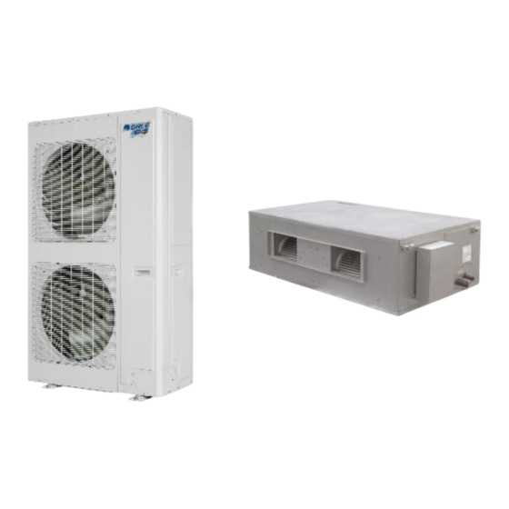
Duct type split Air conditioner Inverter Series 1 Product List Cooling Heating Appearance Capacity Capacity Product Power Model Refrigerant Code Supply Outdoor Indoor FGR20Pd/ CF01000 DNa-X(Au) 3N/380 415V/5 R410a 0Hz/ 60Hz FGR24Pd/ CF01000 DNa-X(Au) 2 Nomenclature Description Options Ducted Type Air Conditioner Cooling only type-omitted Unit type Heat pump-R... -
Page 5: Specifications
Duct type split Air conditioner Inverter Series 3 Specifications Model Heat pump FGR20Pd/DNa-X(Au) FGR24Pd/DNa-X(Au) Cooling Capacity Heating AEER/ACOP 3.17/3.18 3.25/3.40 Power supply Ph/V/Hz 3N/380-415/(50/60) 3N/380-415/(50/60) 7.12 Cooling Power input 7.02 Heating 11.2 12.69 Cooling Current input 12.3 12.51 Heating Refrigerant charge volume... -
Page 6: Control
Duct type split Air conditioner Inverter Series CONTROL... -
Page 7: Wired Controller
Duct type split Air conditioner Inverter Series 1 Wired Controller 1.1 Control panel Fig.2.1 Appearance of wired controller Fig2.2 LED graphics of wired controller Table 2.1 LED display instruction Symbols Instructions Up and down swing function Left and right swing function It's valid under Save mode and displays during setting process. - Page 8 Duct type split Air conditioner Inverter Series Symbols Instructions Fan mode Heating mode When inquiring or setting project number of indoor unit, it displays "NO." icon Floor Heating mode (When Heating and Floor Heating simultaneously shows up, it indicates 3D Heating is activated.) Display "SET"...
- Page 9 Duct type split Air conditioner Inverter Series Button Graphics: Fig.2.3 Button graphics 1.2 Installation and removal 1.2.1 Installation dimensions Fig.2.4 Installation dimensions 1.2.2 Installation method Fig.2.5 Installation of Wired Controller Above is a simple installation method of wired controller. Please pay attention to the following: (1) Before installation, disconnect power of the indoor unit.
- Page 10 Duct type split Air conditioner Inverter Series (2) Pull out the 2-core twisted pair cable from the installation hole on the wall and lead it through the hole on the back plate of wired controller. (3) Place the wired controller on wall and secure its back plate on wall with screw M4X25. (4) Connect the 2-core twisted pair cable to terminal H1 and terminal H2.
-
Page 11: Remote Controller Yap1F
Set timer on function Set left&right swing status Set fan speed 3 Monitoring Software 3.1 Function introduction Integrating with telecommunication technology and computing software, Gree Commissioning Tool Kits can realize the comprehensive monitor, control and commissioning on central air conditioners. It is... - Page 12 The 1st part is the monitoring computer, including Gree debugger and Gree USB converter driver that are installed in the computer. The 2nd part is Gree USB converter, which is to convert the air conditioning communication into computing communication. This part is made up of Gree USB data converter and USB data wire.
- Page 13 Duct type split Air conditioner Inverter Series 3.3.2.2 Appearance 3.3.2.3 Operation instruction (1) Power LED: a red light. If the red light is on, it indicates normal power supply. If the red light is off, it indicates the power supply of converter is not normal. (2) Communication LEDs: yellow lights.
- Page 14 (8) HBS interface: When HBS converter is under HBS communication mode, connect air conditioner’s HBS data interface. HBS interface exhibits no polarity (This interface is not yet available for Gree debugger and the monitoring software). (9) RS485 interface: When RS485 converter is under RS485 communication mode, connect air conditioner’s RS485 data interface.
- Page 15 (5)Applicable to multiple series, models and users Gree Commissioning Tool Kits is applicable to air conditioning system that comsists of multiple series and models. Later, it will be developed to cover all series of Gree central air conditioners,...
- Page 16 Put the CD into the CD-ROM. If it’s automically running, then the following display will be shown. Or double-click the file “Launcher.exe”. For the first time to use Gree Commissioning Tool Kits, install these programmes: .Net Framework 4.0, USB Data Converter, Access Driver (necessary for versions below OFFICE 2007), Gree Debugger.
- Page 17 Duct type split Air conditioner Inverter Series 3.4.1.1 Installation flowchart Button Graphics This flowchart describes basically the software installation process. See below for details. 3.4.1.2 Installation process (1) Install .Net Framework 4.0 If your computer has installed .Net Framework 4.0 or versions above, there’s no need to install again.
- Page 18 Duct type split Air conditioner Inverter Series Extracting files Click and select “I have read and accept the license terms”. Then click “Install”.
- Page 19 Duct type split Air conditioner Inverter Series Installation is in progress. Click “Finish” to complete the installation.
- Page 20 Duct type split Air conditioner Inverter Series (2) Install Access Driver Before operating Gree commissioning software, please first install Access Driver (necessary for versions below OFFICE 2007). Click “Install Access Driver”. Click ”Next”.
- Page 21 Duct type split Air conditioner Inverter Series Tick “I accept the terms in the License Agreement” and then click “Next” Click “Browse” to change the default folder to the expected one, or click “Install” to continue the installation.
- Page 22 Duct type split Air conditioner Inverter Series Installation is in progress. Click “Ok” to complete the installation.
- Page 23 Duct type split Air conditioner Inverter Series (3) Install Gree Debugger Before installing Gree debugger, make sure that your computer is installed with .Net Framework 4.0 or versions above. Then click “Install Gree Debugger”. Click “Next”.
- Page 24 Duct type split Air conditioner Inverter Series Click “Browse” to select installation folder. If no change is needed for the folder, click “Next” to continue the installation. Click “Next”.
- Page 25 Duct type split Air conditioner Inverter Series Installation is in progress. Click “Close” to complete the installation.
- Page 26 Duct type split Air conditioner Inverter Series (4) Install USB Converter Driver If USB converter driver is already installed in your computer, this part can be skipped. Otherwise, click “Install USB Converter Driver”. Then the following installation window will be shown.
- Page 27 Duct type split Air conditioner Inverter Series This window will exit after installation is finished. (5) Install Gree USB Data Converter If converter baud rate is needed to be set, then converter configuring software must be installed. Click “Install Gree USB Data Converter”.
- Page 28 Duct type split Air conditioner Inverter Series Click “Next”. Tick “I accept the agreement”. Then click “Next” to continue installation.
- Page 29 Duct type split Air conditioner Inverter Series Click “Browse” to select your expected installation folder. Click “Next” to continue. Click “Browse” to change folder. Click “Next” to continue.
- Page 30 Duct type split Air conditioner Inverter Series If you want to create s desktop shortcut, tick “Creat a desktop icon”. Then click “Next” to continue. Destiniation location, folder and additional task will be shown in the next step. If you need to change any of it, please click “Back”.
- Page 31 Duct type split Air conditioner Inverter Series Installaiton is in progress. 10) Click “Finish” to complete the installation. 3.4.2 Data monitoring (1) Start up Gree Debugger.
- Page 32 Duct type split Air conditioner Inverter Series (2) On the original interface, user can select language and units system. Click “OK” to confirm the defaulted language and units system and start up the software. (3) Select language.
- Page 33 Duct type split Air conditioner Inverter Series (4) Select system of units. (5) If units you want to monitor are already connected, and able to communicate normally, with correct COM and protocal, then you may click “Connect” to enter the interface of numbers. Otherwise, connect in accordance with the connection diagram shown below.
- Page 34 Duct type split Air conditioner Inverter Series (6) COM selection: the serial port in your computer can be detected automatically. You just need to select your desired serial port. (7) Protocal selection: This is to select the communication method of your units. Currently, CAN is applicable to the units.
- Page 35 Duct type split Air conditioner Inverter Series (8) After the selection, click “Connnect”. If units can communicate normally with computer, then the interface of numbers will be shown soon. Otherwise, “Connecting” will be shown. (9) There are several display zones on this interface. You can hide devices information and system information by clicking devices information icon and system icon .
- Page 36 Duct type split Air conditioner Inverter Series of outdoor modules information, it can show information of only one module and hide information of others (two modules are defaulted to be shown). Menu bar can be hidden by clicking icon Status bar shows the current time and period for data collection. Menu bar Title bar Error display...
- Page 37 Duct type split Air conditioner Inverter Series (2) Click “Start” to enable the debugging function. Then debugging will be started up automatically. indicates that debugging is in progress while indicates debugging is completed. (3) If “OK” button is displayed, it means user needs to judge whether to continue debugging or not. Click and relevant information will be shown for your reference.
- Page 38 Duct type split Air conditioner Inverter Series (4) Icon indicates that there is problem found during debugging. Debugging will not be completed unless problem is solved (after problem is solved, step without “OK” button will switch to the next step automatically, otherwise user needs to click “OK” to continue). Click icon and relevant information detected in this step will be displayed for your reference in order to solve problems.
- Page 39 Duct type split Air conditioner Inverter Series 3.4.4 Control units (1) Click icon of “Setting” on menu bar and select parameter settings, which include “Gateway Settings”, “IDU Settings”, “System Settings”, “Project Number Conflict (In case there is project number conflict in indoor units, other functions will be shielded.
- Page 40 Duct type split Air conditioner Inverter Series (3) Tick the indoor units that need setting in the IDU selection zone or you may click “Select All” to select all of them or “Select Inverted” to select none of them. After selection, the current values of the corresponding parameters will be displayed in the zone of settings.
- Page 41 Duct type split Air conditioner Inverter Series 3.4.5 Other functions Capture screen (1) Click icon of “Capture Screen” to print the interface. If you want to open the interface, click “Open”.
- Page 42 Duct type split Air conditioner Inverter Series Search for database folder (2) Click icon of “Open Data Folder” on the menu bar to open database folder.
- Page 43 Duct type split Air conditioner Inverter Series Conversion of pressure value (3) Click icon of “Others” on the menu bar and then click “Display Settings” to select “High Low Pressure Value” and “Refrigerant Type”. Select “Temperature” and the pressure parameter displayed on the interface will be temperature.
- Page 44 Duct type split Air conditioner Inverter Series Database saving of multiple systems (4) Click icon of “Others” on the menu bar and click “Database Save Settings” to select which system that needs to save database. Because there is a large quantity of data in a network that contains multiple systems, data of only one system can be saved.
- Page 45 Duct type split Air conditioner Inverter Series Change database saving path and rebuild database (5) Change of database saving path and rebuilding of database should be set before the software starts monitoring (see below interface). Click “Change database saving path” and click “Browse” to change the saving path.
- Page 46 LEDs. Notice: If it’s the first time your PC uses Gree USB data converter, in order to prevent Gree USB data converter from being mistaken by your computer as other devices and make sure your mouse can work well, it is necessary to turn off the Serail Enumerator of computer after Gree USB data converter is connected.
- Page 47 Duct type split Air conditioner Inverter Series...
- Page 48 Duct type split Air conditioner Inverter Series Step 3: Right-click ”USB Serial Port (COM6) and then click ”Properties”. The dialog box of properties will then pop up. Step 4: Then click ”Port Settings” in the dialog box.
- Page 49 Duct type split Air conditioner Inverter Series Step 5: Click ”Advanced” and then a new dialog box will pop up. Find the ”Serial Enumerator” in the miscellaneous options and cancel the tick. Click ”OK” to exit.
- Page 50 Duct type split Air conditioner Inverter Series Usage of converter configuring software: (4) When the converter is working, hold the button ”SET” for 5 sec. Function LED will be flickering, indicating that the converter has enter the baud rate setting mode. Then you can use the converter configuring software to set the baud rate of converter.
- Page 51 Duct type split Air conditioner Inverter Series (6) Select the needed communication serial port and language in the “System Settings”. (7) Select the function that is to be set and the corresponding baud rate (refer to the look-up table) in the “Converter Setup”.Then click “Set”.
- Page 52 Duct type split Air conditioner Inverter Series (8) If you want to restore ex-factory settings, click “Default” to restore the default settings. (9) Click “Get” to get the current setting details of converter.
- Page 53 Duct type split Air conditioner Inverter Series (10) Switchover of Software Languages...
-
Page 54: Installation
Duct type split Air conditioner Inverter Series INSTALLATION... -
Page 55: Engineering Installation Preparation And Notice
Duct type split Air conditioner Inverter Series 1 Engineering Installation Preparation and Notice 1.1 Installation notice Personnel and property safety are highly concerned during the entire installation process. Installation implementation must abide by relevant national safety regulations to ensure personnel and property safety. - Page 56 Duct type split Air conditioner Inverter Series Problems that usually occur during installation are as follows: Description of each stage of debugging progress —— Debugging Code Instruction for Code and Operating Method Progress Display Display Code Code There is no master unit in the system. The system cannot Display 01/CC continue to conduct debugging, and all the buttons are invalid...
-
Page 57: Installation Materials Selection
Duct type split Air conditioner Inverter Series Description of each stage of debugging progress —— Debugging Code Instruction for Code and Operating Method Progress Display Display Code Code conduct with care) If the ODU is continuously energized for ≥8h, or the continous 8-hour energizing time in the last time till now is less than 2 Display 08/oC... - Page 58 Duct type split Air conditioner Inverter Series R410A Refrigerant System OD (mm/inch) Wall Thickness (mm) Model Ф15.9(5/8) Ф19.05(3/4) Ф22.20(7/8) Ф25.40(8/8) (6) After the inner part of the copper pipe is cleaned and dried, the inlet and outlet must be sealed tightly by using pipe caps, plugs or adhesive tapes.
-
Page 59: Installation Of Indoor Unit
(3) Angle steel: 30mm×30mm×3mm or above; (4) Round steel: Φ10mm or above 3 Installation of Indoor Unit 3.1 Outline and installation dimension 20kW \24kW Below are dimensions of A, B, C, etc. for different models: Unit: mm Model FGR20Pd/DNa-X(Au)(I) 1541 1350 FGR24Pd/DNa-X(Au)(I) 1541 1350... - Page 60 Duct type split Air conditioner Inverter Series 3.2 Installation space 3.3 External static pressure setting and reading 3.3.1 External static pressure setting You can enter P67 select the way of adjusting static pressure for the blast pipe manually or automatically.The default value is 00,which means adjusting manually. (1) If you choose 00,you can select the suitable level for any blast pipes.
- Page 61 Duct type split Air conditioner Inverter Series Note: ① Under parameter setting status, FAN, TIMER, SLEEP and SWING button are invalid. Press ON/OFF button to go back to home page, but not turning on/off the unit. ② If the power cord is more than 15 m (49-1/4 ft.) long, please increase properly the sectional area of power cord to avoid overload, which may cause accident.
-
Page 62: Installation Of Outdoor Unit
(2) Please contact the local Gree appointed service center before installation. Any malfunctioncaused by the unit that is not installed by the Gree appointed service center would probably not be dealt with on time because of the inconvenience of the business contact. - Page 63 Duct type split Air conditioner Inverter Series 4.3 Carrying and installing outdoor unit When carrying the outdoor unit, hang the unit in four directions with two sufficient ropes. In order to avoid excursion from the center, the angel of ropes must be smaller than 40º during hanging and moving. 4.4 Installation notices In order to ensure proper operation, the selection of installation site must conform to the following principle:...
-
Page 64: Installation Of Drain Pipe
Duct type split Air conditioner Inverter Series Unit: mm Model FGR20Pd/DNa-X(Au)(O) 1615 FGR24Pd/DNa-X(Au)(O) 1615 4.7 Installation space requirement If all sides of the ODU (including the top) are surrounded by walls, process according to the following requirements for installation space: 5 Installation of drain pipe 5.1 Precautions When Doing the Piping Work... - Page 65 Duct type split Air conditioner Inverter Series For example: (2) Keep pipe size equal to or greater than that of the connecting pipe. (3) Install the drain piping as shown and take measures against condensation. Improperly rigged piping could lead to leaks and eventually wet furniture and belongings. (4) When directly connecting a hard vinyl chloride pipe joint to the drain hose connected to the indoor unit, use a commercially available hard vinyl chloride pipe joint (nominal diameter 13mm).
- Page 66 Duct type split Air conditioner Inverter Series of outdoor air. Therefore, U-type water trap shall be designed on the drainage side of each indoor unit. (5) Install water trap as shown below (6) Install one water trap for each unit (7) Installation of water trap shall consider easy cleaning in the future.
-
Page 67: Electrical Installation
Duct type split Air conditioner Inverter Series NO3: Connection of horizontal pipe (10) When unifying multiple drain pipes, install the pipes as shown below. Select converging drain pipes whose gauge is suitable for the operating capacity of the unit.(take the cassette type unit for example) 5.3 Testing of Drain Piping (1) After piping work is finished, check if drainage flows smoothly. - Page 68 Duct type split Air conditioner Inverter Series (9) The earthed resistance must meet the requirements of local national standard. (10) There should be reliable earthed terminal for the power supply. Never connect the earth lead to the following articles: ①water pipe; ②gas pipe; ③drain pipe; ④unreliable place considered by professionals.
-
Page 69: Maintenance
Duct type split Air conditioner Inverter Series MAINTENANCE... -
Page 70: Troubleshooting
Duct type split Air conditioner Inverter Series 1 Troubleshooting Display Display Display Content Content Content code code code Wrong number of indoor Malfunction of Malfunction of water unit for one-to-more indoor unit temperature sensor indoor unit Indoor fan Wrong series for one-to- Malfunction of jumper cap protection more indoor unit... -
Page 71: Wiring Diagram
Duct type split Air conditioner Inverter Series Display Display Display Content Content Content code code code Circuit malfunction of Low voltage protection for driven current Phase-losing of inverter driven DC bus bar of detection for compressor compressor compressor Malfunction of driven Failure start up for inverter AC current protection for charging loop for... - Page 72 Duct type split Air conditioner Inverter Series FGR20Pd/DNa-X(Au)(I);FGR24Pd/DNa-X(Au)(I): FGR20Pd/DNa-X(Au)(O):...
- Page 73 Duct type split Air conditioner Inverter Series FGR24Pd/DNa-X(Au)(O):...
-
Page 74: Disassembly And Assembly Procedure Of Main Parts
Duct type split Air conditioner Inverter Series 3 Disassembly And Assembly Procedure Of Main Parts Introduction to Main Parts Disassembly and Assembly of Compressor Remark: Make sure that there isn’t any refrigerant in pipe system and the power supply is cut off before removal of the compressor Step Illustration... - Page 75 Duct type split Air conditioner Inverter Series Disassembly and Assembly of 4-way valve Remark: Make sure that there isn’t any refrigerant in pipe system and the power supply is cut off before removal of 4-way valve. Step Illustration Handling Instruction Place electric coils far away from the 4-way valve to prevent the Remove electric coils of 4- way...
-
Page 76: Exploded Views And Part List
Duct type split Air conditioner Inverter Series 4 Exploded Views And Part List 4.1 Indoor Unit Model: FGR20Pd/DNa-X(Au)(I)、FGR24Pd/DNa-X(Au)(I) 、 Exploded View: FGR24Pd/DNa-X(Au)(I) Model FGR20Pd/DNa-X(Au)(I) CF010N0770 Product Code CF010N0780 Part Code Part Name Part Code 11724102 Filter Sub-Assy 11724102 0128430401 Water Tray Assy... - Page 77 10300400004701 Motor for Centrifugal Fan(Right Type) 10300400004701 15704100009 Brushless DC Motor 15704100009 103004000047 Motor for Centrifugal Fan(Left Type) 103004000047 4.2 Outdoor Unit Model: FGR20Pd/DNa-X(Au)(O) Exploded View: Model FGR20Pd/DNa-X(Au)(O) Product Code CF010W0780 Part Name Part Code Front Grill 01572800003 Diversion Circle...
- Page 78 Duct type split Air conditioner Inverter Series Model FGR20Pd/DNa-X(Au)(O) Product Code CF010W0780 Part Name Part Code Compressor and Fittings 00204100033 15704100010/ Brushless DC Motor 1570410001001 Motor Support Assy 000046000057 Electrical Heater(Compressor) 7651521212 Oil Separator 07424100050 Cut off Valve 07334100011 Cut off valve...
- Page 79 Duct type split Air conditioner Inverter Series Model: FGR24Pd/DNa-X(Au)(O) Exploded View: Model FGR24Pd/DNa-X(Au)(O) Product Code CF010W0770 Part Name Part Code Front Grill 01572800003 Diversion Circle 10474100003 Cabinet 01514100016P Front Side Plate 01314100091P Handle 26235253 Axial Flow Fan 10434100008 Brushless DC Motor 15704100010 Brushless DC Motor 1570410001001...
- Page 80 Duct type split Air conditioner Inverter Series Model FGR24Pd/DNa-X(Au)(O) Product Code CF010W0770 Part Name Part Code 4-way Valve 43000339 Gas-liquid Separator 07424100048 One way Valve 04324001 Electronic Expansion Valve 43044100190 Reactor 4313017401 Terminal board 42000100000401 Terminal board 420001000019 Main Board 30223000039 Electric Box Assy 100002062075...
- Page 81 JF00303776...
Need help?
Do you have a question about the FGR20Pd/DNa-X and is the answer not in the manual?
Questions and answers