Gree CAS12HP230V1AC Installation Manual
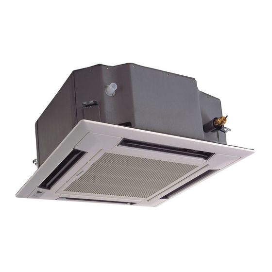
Multi 21 ceiling cassette
Hide thumbs
Also See for CAS12HP230V1AC:
- Installation manual (24 pages) ,
- Technical product manual (17 pages) ,
- Owner's manual (31 pages)

Related Manuals for Gree CAS12HP230V1AC


Summary of Contents for Gree CAS12HP230V1AC
-
Page 1: Installation Manual
CEILING CASSETTE INSTALLATION MANUAL Models: CAS12HP230V1AC CAS18HP230V1AC CAS24HP230V1AC... -
Page 2: Table Of Contents
Thank you for choosing a Multi21 Ceiling Cassette Ductless Heat Pump System for your customer. Please read this installation manual carefully before installing and starting up the Ceiling Cassette Ductless System.Take a moment to fill out the product and installation form on the back cover. Retain both the manual and installation record for future reference. -
Page 3: Safety Precautions
SAFETY PRECAUTIONS Please read the following before installation. This is the safety alert symbol. It is used to alert you to potential personal injury hazards. Obey all safety messages that follow this symbol to avoid possible injury or death. This mark indicates procedures which, if improperly performed, W RNING might lead to the death or serious injury of the user. -
Page 4: Nomenclature
NOMENCLATURE Example: CAS18HP230V1AC CAS 18 HP 230V 1 Product Type S - System Series Designation O - Outdoor units CAS - Ceiling Cassette H - Indoor High Wall D - Indoor Duct C - Indoor Cassette F - Indoor Floor/Ceiling Cooling Capacity 12 - 12,000 BTUH 18 - 18,000 BTUH... -
Page 5: Suggested Tools
SUGGESTED TOOLS • Standard Wrench • Adjustable/Crescent Wrench • Torque Wrench • Hex Keys or Allen Wrenches • Drill & Drill Bits • Hole Saw • Pipe Cutter • Screw drivers (Phillips & Flat blade) • Manifold and Gauges • Level •... -
Page 6: System Parts
SYSTEM PARTS Indoor unit Air outlet Air inlet Part Name 1. Power Supply and Communication Wires 2. Drain Pipe 3. Liquid Pipe 4. Decorative Discharge Air Grille (sold separately) 5. Gas Pipe 6. Wired Tether Controller 7. Remote Controller 8. Service Cover Air inlet 9. -
Page 7: Installation Site Instructions
INSTALLATION SITE INSTRUCTIONS Indoor Unit W RNING The unit must be installed in a location which can withstand four times the weight of the unit. Inadequate support may result in serious property damage and injuries. Select a site that allows for the following: Ensure the installation complies with the installation minimum dimensions and meets the •... -
Page 8: Indoor Unit Dimensions
INDOOR UNIT DIMENSIONS 12-18K Indoor Unit Dimensions Suction/Gas Line Liquid Line Drain Line Model Port Size Port Size Connection 12,000 3/8-in OD Flared 1/4-in OD Flared 1.2-in OD 18,000 1/2-in OD Flared 1/4-in OD Flared 1.2-in OD... - Page 9 INDOOR UNIT DIMENSIONS 24K Indoor Unit Dimensions Drain Line Suction/Gas Line Liquid Line Port Size Port Size Connection 5/8-in OD Flared 3/8-in OD Flared 1.2-in OD Laying Out Indoor Location • Locate the factory supplied installation template included in carton. •...
-
Page 10: Indoor Unit Installation
INDOOR UNIT INSTALLATION Indoor Unit Hanger Mounting Depending on the type of ceiling, attach the threaded hanger bolts securely to the support stud. Before lifting the indoor unit to the installation location, insert the upper nuts, flat washers (with insulation), flat washers (without insulation), lower nuts and double locking nuts on the threaded hanger bolts. -
Page 11: Piping Installation
PIPING INSTALLATION Refrigerant Piping Drill Hole in Wall Indoor Outdoor 1. Locate and mark proper location for the wall hole. Wall Hole Sleeve 2. Cut the 2 3/4” wall hole with a 5° to 10° Seal Hole downward slant to the outdoors. 3. - Page 12 PIPING INSTALLATION Connecting Refrigerant Pipes to Ceiling Cassette 1. Feed refrigerant pipes, drain hose and communication cable assembly through wall hole from outdoor to the Ceiling Cassette. 2. Pull the piping assembly to the indoor unit. Carefully bend refrigerant pipes to meet indoor unit connection ports.
- Page 13 PIPING INSTALLATION Outdoor Unit Pipe Connections WARNING Indoor Condensate Drain Piping CAUTION W RNING WARNING Observe all local sanitary codes when installing condensate drains. It is recommended to install the condensate drain system with hard polyvinyl chloride (PVC) pipe and matching connectors. Use piping of the same diameter or larger as the unit connection. The Ceiling Cassette drainage port diameter is 1.2 in.
- Page 14 PIPING INSTALLATION Vertical Lift Drainage System If a gradual pitch from the drainage port is not obtainable, the Ceiling Cassette contains an internal condensate drain pump with limited head or lift.The condensate drain pipe may have a vertical height of 11-in.
-
Page 15: Power & Wiring
POWER AND WIRING INSTALLATION WARNING CAUTION W RNING WARNING 1. Before obtaining access to wire terminals, all electrical supply circuits must be disconnected, locked out and tagged. 2. Always use an independent (dedicated) circuit and provide an independent (dedicated) circuit breaker to supply power to the system. 3. -
Page 16: Power And Wiring Installation
POWER AND WIRING INSTALLATION Electric Wiring Between Indoor Unit and Outdoor Unit Wired Tether Controller XK-19 White Cassette Unit Typical Wiring Diagram Black Green Power: Outdoor Electrical Wiring For Outdoor Unit wire connections, see installation instructions shipped with the outdoor unit. WARNING Electrical Connections to Ceiling Cassette CAUTION... -
Page 17: Power & Wiring
POWER AND WIRING INSTALLATION Indoor Disconnect Switch (Optional) Local codes may require a disconnect switch within sight of the indoor unit. Use a DFS Disconnect Switch Accessory Kit (Part No: DFS-SWITCH-A) to break interconnecting wires going to the N(1), 2, 3, terminals on the indoor unit, as shown in the wiring diagram below: Disconnect Switch Indoor Unit Outdoor Unit... -
Page 18: Controller Installation And Setup
CONTROLLER INSTALLATION AND SETUP (Optional) The following is a brief overview of the Wired Tether Controller installation. See Tether Controller Owner's Manual for more detailed instructions for setup and operation. Preparation for Installation Select a proper location on the wall for mounting the Tether Controller. -
Page 19: Fresh Air Intake
FRESH AIR INTAKE (24K Size Only) Connecting Fresh Air Duct The indoor ceiling cassettes have a fresh air intake port for ventilation. A booster fan and duct (field supplied) must be used to feed outdoor air to the indoor unit. Determine the duct diameter, length and booster fan size based on the required airflow. -
Page 20: Decorative Grille Installation
DECORATIVE GRILLE INSTALLATION Mounting Decorative Grille Ceiling Cassette Refrigerant main body pipes 1. Carefully unpack decorative grille and align the Hook & latch decorative grille to the Ceiling Cassette main body. 2. Temporarily attach the decorative grille to the Hook & latch ceiling cassette main body at two (2) corner points. -
Page 21: Testing And Inspection
TESTING AND INSPECTION Start-up Checklist Turn on main power to indoor and outdoor units. • Verify the system is not displaying an error code on the indoor unit display. Point the Remote Controller at the Ceiling Cassette and Press the On button. •... -
Page 22: Troubleshooting
TROUBLESHOOTING PROBLEM CAUSE/SOLUTION System does not restart. Cause: The system has a built-in three-minute delay to prevent short and/or rapid cycling of the compressor. Solution: Wait three minutes for the protection delay to expire. Cause: Typically unpleasant odors are the result of mold or mildew forming on the coil surfaces Indoor unit emits unpleasant odor or the air filter. -
Page 23: Diagnostic Codes
DIAGNOSTIC CODES Troubleshooting The unit has onboard diagnostics. The outdoor unit will provide status indicators. The indoor wall unit and remote controller will display error codes. The following is a summary of the codes with explanation: Indoor Unit Outdoor Unit Indicators Malfunction Name Possible Causes &... - Page 24 DIAGNOSTIC CODES Outdoor Unit Indicators Indoor Unit Malfunction Name Possible Causes Display Yellow High Temperature 6 flashes 1) Incorrect refrigerant charge level Resistant Protection and 1 sec Off 2) Refrigerant metering device malfunction 3) Compressor malfunction Cold Air Protection 1) Indoor coil has not reach minimum heating temperature 2) Indoor ambient is abnormally cold 3) Indoor control board malfunction EEPROM Memory Malfunction...
- Page 25 DIAGNOSTIC CODES Outdoor Unit Indicators Indoor Unit Malfunction Name Possible Causes Display Yellow Indoor Coil Freeze Protection - 4 flashes 1) Indoor coil has not reach minimum heating temperature Frequency Decrease/Limit Mode and 1 sec Off 2) Indoor ambient is abnormally cold 3) Indoor control board malfunction Pump Down or Gathering 17 flashes...
- Page 26 DIAGNOSTIC CODES Outdoor Unit Indicators Indoor Unit Malfunction Name Possible Causes Display Yellow Incompatible Indoor and 16 flashes Indoor and outdoor units are not compatible Outdoor Units and 1 sec Off Defrosting Status note 1 16 flashes and 1 sec Off Compressor Phase Current 1) IPM module malfunction Protection...
-
Page 27: Installation Record
UNIT INFORMATION Outdoor Unit: Model No. Serial No. Indoor Unit: Model No. Serial No. INSTALLATION INFORMATION Date Installed: DEALERSHIP/INSTALLER INFORMATION Company Name: Address: Phone Number: Technician Name: Gree Electric Appliances, Inc ©2016 Cat No: DFS-CASS-HP-2IN v2.0...
Need help?
Do you have a question about the CAS12HP230V1AC and is the answer not in the manual?
Questions and answers