
Related Manuals for ARB AIRLOCKER RD196


Summary of Contents for ARB AIRLOCKER RD196
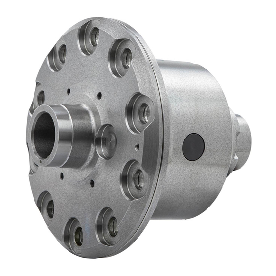
- Page 1 RD196 NISSAN C200K, 31 SPLINE AIR OPERATED LOCKING DIFFERENTIAL INSTALLATION GUIDE...
- Page 2 No liability is assumed for damages resulting in the use of the information contained herein. ARB Air Locker Air Operated Locking Differentials and Air Locker are trademarks of ARB Corporation Limited. Other product names used herein are for identification purposes only and may be trademarks of their respective owners.
-
Page 3: Table Of Contents
Table of Contents: 1 Introduction 1.1 Pre-Installation Preparation 1.2 Tool-Kit Recommendations 1.3 Assembly Type Identification 2 Removing the Existing Differential 2.1 Vehicle Support 2.2 Differential Fluid Drain 2.3 Disconnecting the Axles 2.4 Marking the Bearing Caps 2.5 Checking the Current Backlash Amount 2.6 Removing the Differential Center 3 Bench Measurement 3.1 Approximate Backlash Shimming... -
Page 5: Introduction
Although your ARB Air Locker comes complete with all the step by step instructions you will need to supplement your vehicle manufacturer’s service manual and install your new differential, ARB recommends that you have your Air Locker installed by a trained professional. -
Page 6: Tool-Kit Recommendations
Either a replacement gasket, or gasket sealant, for your differential cover. A sufficient volume of differential oil to completely refill your housing. (see the ARB Air Locker Operating and Service Manual for recommended lubricants) A soap and water mixture to test for air leaks. -
Page 7: Assembly Type Identification
1 Introduction Assembly Type Identification IMPORTANT: Sections 2 and 3 of this installation guide have been written to accommodate two different Nissan C200K applications: the Independent Front Suspension (IFS) type. (Refer to Fig.1.) the live axle Salisbury type. (Refer to Fig.2.) To eliminate confusion, you should identify which figure your vehicle matches with. -
Page 8: Removing The Existing Differential
2 Removing the Existing Differential Vehicle Support Safely secure the vehicle on a hoist. We recommend supporting the vehicle on a chassis hoist to keep the differential area at a convenient working height and to leave the wheels and axles free to be rotated and removed. -
Page 9: Disconnecting The Axles
Any misalignment of the axle tubes may result in excessive wear and/or failure of your differential and axle shafts. ARB strongly recommends that you have your axle assembly inspected for concentricity and straightness before installing your Air Locker. -
Page 10: Marking The Bearing Caps
2 Removing the Existing Differential Marking the Bearing Caps Using a pointed center punch, gently mark the bearing caps in a way that will enable you to know which cap is ‘LEFT’ and which cap is ‘RIGHT’, which way is ‘UP’ and which way is ‘DOWN’. (Fig.3.) HINT : Many installers choose to make one punch mark on the left hand side of the left hand bearing cap and one... -
Page 11: Checking The Current Backlash Amount
2 Removing the Existing Differential Checking the Current Backlash Amount IMPORTANT: This step is a precautionary measure recommended by ARB due to the fact that some after market ring and pinion sets have been manufactured to run with different backlash settings than those specified by your vehicle manufacturer. -
Page 12: Removing The Differential Center
2 Removing the Existing Differential Removing the Differential Center IMPORTANT: YOU MUST SPREAD THE HOUSING ON CAST IRON MODELS Spreading the differential housing with a differential case spreader is a step which is critical to set up bearing pre-load on cast iron differential housings. - Page 13 2 Removing the Existing Differential Once the housing has been adequately spread, the differential may be removed by pulling forward on the differential carrier. NOTE : The differential center is heavy and quite difficult to handle when covered in oil. Take care not to drop it. ...
- Page 14 2 Removing the Existing Differential Live Axle 2.3.2 Remove both bearing caps. Carefully spread the housing (Fig.6.) enough to remove the differential center. (Refer to your vehicle’s service manual). NOTE : Do not spread the housing more than 0.50mm [0.020”]. HINT : Be sure not to mix up the left and right hand bearing cups.
-
Page 15: Bench Measurement
3 Bench Measurement Approximate Backlash Shimming In order to reproduce a similar pre-load and ring and pinion backlash in your Air Locker to that of your original differential, measurements need to be taken so that a shim thickness can be calculated. ... - Page 16 3 Bench Measurement Using a caliper or similarly accurate measurement method (i.e., able to take accurate measurements within 0.04mm [0.0015”]), measure the distance from the shoulder of the bearing journal to the ring gear mounting face (shown as ‘A’ in Fig.7.) and record this measurement as ‘A’.
-
Page 17: Calculation & Selection Of Shims
3 Bench Measurement Calculation & Selection of Shims Ideally, the measurement you recorded as ‘C’ from the Air Locker differential will closely match ‘A’ on the existing differential (within 0.1mm [0.004”] ) and then the factory shim can be reused, however, quite often these measurements will vary slightly between one factory differential and the next. -
Page 18: Installing The Air Locker
4 Installing the Air Locker Insuring Adequate Oil Drainage IMPORTANT: Some Salisbury axles were manufactured with poor oil drainage between the axle tubes and the differential housing. This can often result in one of the axle tubes filling up with differential oil while running. -
Page 19: Installing The Carrier Bearings
4 Installing the Air Locker NOTE : Make sure any grinding dust, filings or drill chips left behind by cutting the drainage slots is completely cleaned out of the housing. Check that the axle air vents are clear and working correctly. Installing the Carrier Bearings ... -
Page 20: Mounting The Ring Gear
4 Installing the Air Locker Mounting the Ring Gear Apply a thin film of high pressure grease to the ring gear shoulder of the Air Locker to prevent seizing. Thoroughly clean any thread locking compound or other foreign matter from the holes of the ring gear, the threads of the ring gear bolts, and the mating surfaces between the ring gear and the Air Locker flange. -
Page 21: Drilling And Tapping The Bulkhead Port
4 Installing the Air Locker Drilling and Tapping the Bulkhead Port An airline port must be drilled and tapped through the differential housing to mount the bulkhead fitting into. NOTE : Higher ratio gearing uses deeper (thicker) ring gears with teeth that extend much further. Make sure the intended hole location is far enough away from the ring gear teeth that the air line will not be at risk of contact with the current or future ring gears. - Page 22 4 Installing the Air Locker Port Location on the Live Axle Housing 4 .4.2 Mark a spot on the top of the outside shell of the differential housing that will be clear of the ring gear position once the seal housing tube has been installed (Figure 12.).
-
Page 23: Assembling The Seal Housing
4 Installing the Air Locker Assembling the Seal Housing Figure 13. Make sure the grooves and airway of the seal housing are clean and free from any contaminants (e.g. water, dirt, metal filings, etc.). Inspect the seal housing O-rings (supplied) for dirt, damage or other conditions which might cause leaks. -
Page 24: Pre-Load Shimming
4 Installing the Air Locker Pre-Load Shimming In order to pre-load the tapered roller bearings in your Air Locker, measurements need to be taken so that a value can be calculated for the shim thickness ‘E’ in Figure 13. IMPORTANT: When installing the Air Locker into the housing, it is critical to check for clearance between the Air Locker case and the pinion gear. - Page 25 4 Installing the Air Locker Push (or lightly pry) the Air Locker hard across to the right-hand side, and measure the maximum gap (also called the ‘end float’) between the left-hand factory shim and the differential housing with an automotive feeler gauge. (Fig.15.) Figure 15.
-
Page 26: Modifying The Bearing Cap
Do not spread the housing more than 0.50mm [0.020”]. NOTE : Use the ARB Shim Driver #0770004 to install the supplied Air Locker shims. Rotate the seal housing until the tube is pointing straight out of the housing. - Page 27 4 Installing the Air Locker Measure the distance from the edge of the bearing cap to the seal housing tube and mark this spot (it should be approximately 8mm). Hold the bearing cap steady for drilling in a soft jawed vice clamp. NOTE : Do not apply too much clamping pressure with the vice.
-
Page 28: Reinstalling The Bearing Caps
4 Installing the Air Locker Reinstalling the Bearing Caps Install the bearing caps oriented as they were marked before they were removed, and tighten the bearing cap bolts. It is not necessary to torque them down at this time. ... -
Page 29: Checking The Backlash
4 Installing the Air Locker Checking the Backlash Set a depth indicator on one of the ring gear teeth as in Figure 18. While supporting the pinion gear by holding the drive shaft, rotate the differential in both directions while observing the maximum variation in depth from the indicator (i.e., the highest value minus the lowest value). -
Page 30: Setting Up The Bulkhead Fitting
4 Installing the Air Locker Re-Shimming the Backlash 4.9.1 NOTE : This step is only necessary when adjusting for incorrect backlash. Remove the bearing caps. Remove the differential as before. To decrease the amount of backlash, reduce the shim thickness ‘D’ (Fig.8.) and increase the shim thickness ‘E’... - Page 31 4 Installing the Air Locker Figure 19. NOTE : Make sure the seal housing tube is all of the way into the center compression nut while you are tightening NOTE : Firmly tighten the center compression nut so that a good seal is formed around the tube.
-
Page 32: Profiling The Seal Housing Tube
4 Installing the Air Locker Profiling the Seal Housing Tube 4.11 Completely remove the differential spreader. Without using sharp, jagged tools such as pliers (usually your hands are the best tool for this job), gently bend the seal housing tube so that it runs along the inside of the differential housing (as shown in Figure 20., and... -
Page 33: Bench Testing The Air Locker
NOTE : An accurate way to test for air leaks is to fit a shut-off valve to an air pressure gauge (ARB part # 0770005). Once 620 KPA [90 PSI] is reached close the valve, disconnect the air hose, and watch to see if there is any drop in pressure. -
Page 34: Modifying The Ifs Assembly
4 Installing the Air Locker Modifying the IFS Assembly 4.13 In order to ensure correct assembly, the Diff Cover and Stub Axle will have to be modified. Grinding the Diff Cover 4.13.1 Grind the rib of the diff cover as shown (Figure 23.) until it clears the Air Locker. - Page 35 4 Installing the Air Locker Figure 24. Figure 25. Grind or machine the end of the axle until you have created enough clearance for the bearing to seat and the circlip to engage properly (Figure 26.). It may be necessary to trial fit the stub axle several times to get this correct.
-
Page 36: Installing The Air System
Mounting & Connecting the Electrical System Mounting the Solenoid Connection to an ARB Air Compressor 5.1.1 (Fig.27.) Remove one of the 1/8” BSP plugs from its port in the compressor tank. Apply Teflon paste to the 1/8” BSP nipple on the solenoid and insert it into the port and tighten. - Page 37 For ease of installation, quality of air supply, and a high level of dependability from your Air Locker(s) , ARB strongly recommends use of a genuine ARB Air Compressor, however, the Air Locker air system can be operated on any alternate air source that meets each of the following guidelines: ...
-
Page 38: Running & Securing The Air Line
Mounting & Connecting the Electrical System Running and Securing the Air Line The path taken by the air line from your air source (i.e., compressor) to your Air Locker is unique to your vehicle and the position of your air source. -
Page 39: Connection To The Bulkhead Fitting
Mounting & Connecting the Electrical System To attach the air line to the push-in fitting of the solenoid; insert the line firmly into the fitting, pull outward on the flange of the fitting while holding the line as far into the fitting as possible, and then gently pull outward on the air line to clamp the line in place. - Page 40 Mounting & Connecting the Electrical System Push the airline into the compression fitting body and screw the outer nut down onto it. Using a 12mm spanner, tighten the outer nut onto the compression fitting body. NOTE : Some force is required to crush the ferrule, however the outer compression nut will tighten against a stop.
-
Page 41: Mounting & Connecting The Electrical System
Switch(es) should not be mounted where they will be exposed to water (e.g., in the lower section of an inner door panel). ARB recommends that you apply the Air Locker Warning Sticker (ARB part # 210101) within close visual proximity of the switch location. -
Page 42: Wiring The Actuator System
Connection to an ARB Air Compressor 6.2.1 When wiring the Air Locker actuator switch(es) and solenoid(s) to an ARB Air Compressor, all connections can easily be set up directly from the supplied wiring loom. (Fig. 30.) NOTE : 180409 model loom shown for reference only. Refer to your ARB Air Compressor Installation Guide for details on configuring your installation. - Page 43 6 Mounting & Connecting the Electrical System Figure 30. SWITCH TERMINAL IDENTIFICATION Figure 31.
- Page 44 6 Mounting & Connecting the Electrical System Connection to an Alternate Air Source 6.2.2 When connecting the actuation switch to an alternate air source, the switch(es) should be wired according to figures 32. and 33., depending on whether one or two Air Lockers will be installed in the vehicle. Single Air Locker System 6.2.2.1 ...
- Page 45 6 Mounting & Connecting the Electrical System Dual Air Locker System 6.2.2.2 If two Air Lockers are to be installed in the system, ARB recommends that the switches and solenoids be wired according to figure 33. For safety reasons, this configuration allows SOLENOID 2 to be actuated only if SOLENOID 1 is already on.
-
Page 46: Testing & Final Assembly
Testing & Final Assembly Leak Testing With the vehicle parked and the engine off, turn the compressor on and wait until the air system is fully charged. NOTE : With the Air Locker(s) disengaged, the air source (i.e., compressor) should not have to recharge over time. Intermittent recharging without Air Locker use usually indicates a leak at the solenoid fittings or at the compressor tank O-ring seal. -
Page 47: Testing The Air Locker Actuation
The wheels should again rotate in opposite directions. Re-Sealing & Filling the Differential NOTE : Consult the ARB Air Locker Operating & Service Manual for recommendations on differential lubricant specifications. Replace the differential cover using gasket sealant or a new standard differential cover gasket for your make of vehicle. -
Page 48: Post-Installation Check List
Testing & Final Assembly Post-Installation Check List Now that the Air Locker installation has been completed, ARB recommends that you take the time to complete the following check list just to insure that you haven’t missed any of the vital steps. -
Page 49: Parts List
Parts List RD196 Nissan C200K, 31 SPL Exploded Assembly Diagram (See itemized parts list overleaf) Figure 34. Specifications Axle Spline 31 tooth, Ø32mm [1.26”] Ratio Supported All Ring Gear ID 128.0mm [5.03”] Ring Gear OD 200mm [7.87”] Ring Gear Bolts 10 bolts on Ø150mm [5.90”] Ring Gear Torque 149 Nm [110 ft-lb] Backlash... -
Page 50: Itemized Parts List
Available only as complete thrust washer kit #730H01 All diffs produced before serial #17070001 came with 5mm air connection system. For information contact ARB. Refer to pinion modification tech note (Sec. 5.6). Part No. 2102196 Revision 27/10/2020 Copyright © 2015 by ARB Corporation Limited...
Need help?
Do you have a question about the AIRLOCKER RD196 and is the answer not in the manual?
Questions and answers