
Related Manuals for ARB RD151


Summary of Contents for ARB RD151
- Page 1 RD151 TOYOTA 8” IFS, 34 SPLINE, 58MM CARRIER BEARING AIR OPERATED LOCKING DIFFERENTIAL INSTALLATION GUIDE...
- Page 2 No liability is assumed for damages resulting in the use of the information contained herein. ARB AIR LOCKER Locking Differentials and AIR LOCKER are trademarks of ARB Corporation Limited. Other product names used herein are for identification purposes only and may be trademarks of their respective owners.
-
Page 3: Table Of Contents
Table of Contents: 1 Introduction 1.1 Pre-Installation Preparation 1.2 Tool-Kit Recommendations 2 Removing the Existing Differential 2.1 Vehicle Support 2.2 Differential Fluid Drain 2.3 Removing the Differential Assembly 2.4 Checking the Current Backlash Amount 2.5 Removing the Differential Center 3 Installing the Air Locker 3.1 Installing the Carrier Bearings 3.2 Approximate Backlash Shimming 3.3 Mounting the Ring Gear... -
Page 5: Introduction
Although your ARB Air Locker comes complete with all the step by step instructions you will need to supplement your vehicle manufacturer’s service manual and install your new differential, ARB recommends that you have your Air Locker installed by a trained professional. -
Page 6: Tool-Kit Recommendations
Suitable measuring tools to measure a differential for preload shimming. (e.g., an automotive feeler gauge) An 11.2mm [7/16”] drill and ¼”NPT tap for bulkhead fitting installation. An automotive bearing puller (e.g., ARB Bearing Puller #0770001). A bearing press or arbor press. Supplies 1.2.2 ... -
Page 7: Removing The Existing Differential
2 Removing the Existing Differential Vehicle Support Safely secure the vehicle on a hoist. We recommend supporting the vehicle on a chassis hoist to keep the differential area at a convenient working height and to leave the wheels and axles free to be rotated and removed. -
Page 8: Checking The Current Backlash Amount
2 Removing the Existing Differential Checking the Current Backlash Amount IMPORTANT: This step is a precautionary measure recommended by ARB due to the fact that some aftermarket ring and pinion sets have been manufactured to run with different backlash settings than those specified by your vehicle manufacturer. -
Page 9: Removing The Differential Center
Remove all bolts from around the outside of the clamshell. Gently pry the clamshell apart and remove the differential center. ARB recommends removing the oil seal from the deep clamshell half at this stage. A replacement seal will be required (Toyota Australia part #9031147012). -
Page 10: Installing The Air Locker
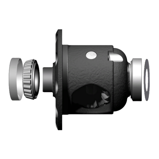
3 Installing the Air Locker Installing the Carrier Bearings Apply a thin film of high pressure grease to both bearing journals of the Air Locker. Using a bearing press or arbor press, press one of the supplied tapered roller bearing cones onto the bearing journal opposite to the ring gear flange of the differential carrier (As shown in Figure 2.) until the bearing seats firmly against the bearing journal shoulder. -
Page 11: Approximate Backlash Shimming
3 Installing the Air Locker Approximate Backlash Shimming In order to reproduce a similar pre-load and ring and pinion backlash in your Air Locker to that of your original differential, measurements need to be taken so that a shim thickness can be calculated. ... - Page 12 Be sure to measure using the bearing cup that originally came off of the right-hand side. Assemble the new bearing cup and 3mm thick ARB master shim (supplied with your Air Locker kit) onto the right-hand side of the Air Locker (as shown in Fig.
- Page 13 Select shims from the shim kit supplied with your Air Locker to make the thickness ‘B’ as determined above. Place this shim pack between the ARB master shim and the bearing cup. Re-measure the new distance ‘C’ from the Air Locker (now including the shim pack ‘B’) to make sure that it matches ‘A’...
-
Page 14: Mounting The Ring Gear
3 Installing the Air Locker Mounting the Ring Gear Apply a thin film of high pressure grease to the ring gear shoulder of the Air Locker to prevent seizing. Thoroughly clean any thread locking compound or other foreign matter from the holes of the ring gear, the threads of the ring gear bolts, and the mating surfaces between the ring gear and the Air Locker flange. -
Page 15: Installing The Bearing Sleeves
3 Installing the Air Locker Installing Bearing Sleeves Using an oven or heat gun, heat both of the clamshell halves to between 130° and 150°C to expand the housings. Make sure that the bearing sleeves (Fig. 6.) and clamshell halves are clean and free from any contaminants (e.g., water, dirt, metal filings, etc.). - Page 16 3 Installing the Air Locker Figure 7. Figure 8.
-
Page 17: Preload Shim Measurement
‘D’ in Figure 9. Figure 9. Assemble the 3mm ARB master shim and the shim pack determined earlier as ‘B’ (Fig.4.) into the bearing bore of the deep half of the clamshell. - Page 18 Assemble any remaining shims from the Air Locker shim kit (supplied) together into one shim pack and measure the total thickness. Include the remaining ARB Master Shim in this measurement. Assemble the shim pack onto the seal housing flange on the same side as the seal housing tube’s solder joint.
-
Page 19: Calculation & Selection Of Preload Shims
3 Installing the Air Locker Calculation & Selection of Preload Shims Consult your vehicle manufacturer’s service manual to determine the carrier bearing preload amount specified for your vehicle. NOTE : If your service manual specifies preload in terms of a torque value measured off the drive pinion flange, then assume a preload amount of 0.6mm [0.024”] for the following calculations. - Page 20 3 Installing the Air Locker Figure 11. Figure 12. NOTE : To best determine the correct vertical position of the drilled hole, measure down from the machined face (shown at the top of the picture in Figure 12.) a distance of 15mm [19/32”] and mark the horizontal line which the hole is centered on.
-
Page 21: Installing The Seal Housing
3 Installing the Air Locker Cover the bearing seat area with a rag to protect the inside of the clamshell from metal filings. Drill through the housing square to the outside surface using an 11.2mm [7/16”] drill. Tap the hole from the outside using a ¼” NPT pipe tap. ... - Page 22 3 Installing the Air Locker Trim the end of the tube to length (as shown in Figure 14.) so that it will poke out of the end of the bulkhead fitting. Figure 14. Make sure the seal housing tube and the grooves of the seal housing are clean and free from any contaminants (e.g., water, dirt, metal filings, etc.).
- Page 23 3 Installing the Air Locker Figure 15. NOTE : Do not use excessive force when pressing as this may damage the seal housing assembly. NOTE : You should not be able to rotate the shim pack underneath the bearing cup if it has been pressed in far enough.
-
Page 24: Setting Up The Bulkhead Fitting
3 Installing the Air Locker Setting Up the Bulkhead Fitting Apply thread sealant to the outside threads of the bulkhead body. Screw the bulkhead body into the tapped hole, and lightly tighten using a 14mm [9/16”] spanner. Wipe the area clean of any excess thread sealant (inside and outside of the housing). -
Page 25: Final Assembly
3 Installing the Air Locker Final Assembly 3.10 Turn the shallow half of the clamshell upside down and insert the Air Locker into the seal housing by gently lowering it through the bearing cup and into the seal housing with a gentle twisting motion. This will allow the O-rings to engage gently. -
Page 26: Checking The Backlash
3 Installing the Air Locker Checking the Backlash 3.11 Refer to your vehicle manufacturer’s service manual for the specified maximum and minimum amounts of backlash. If the backlash measured here is not within the specifications then the differential will have to be re-shimmed. ... - Page 27 3 Installing the Air Locker Re-Shimming the Backlash 3.11.1 NOTE : This step is only necessary when adjusting for incorrect backlash. Remove the bolts from the clamshell housing. With the shallow half of the clamshell sitting firmly on a horizontal surface, lift off the deep half of the clamshell.
-
Page 28: Bench Testing The Air Locker
NOTE : An accurate way to test for air leaks is to fit a shut-off valve to an air pressure gauge. (ARB part # 0770005 shown in Fig.18.). Once 620 KPA [90 PSI] is reached close the valve, disconnect the air hose, and watch to see if there is any drop in pressure. -
Page 29: Reinstalling The Differential Assembly
3 Installing the Air Locker Reinstalling the Differential Assembly 3.13 Reassemble the differential assembly according to your vehicle manufacturer’s service manual using gasket sealant where necessary. Press in the new replacement oil seal for the deep half of the clamshell (Toyota Australia part #9031147012). -
Page 30: Installing The Air System
4 Installing the Air System Mounting the Solenoid Connection to an ARB Air Compressor 4.1.1 (Fig.19.) Remove one of the 1/8” BSP plugs from its port in the compressor tank. Apply Teflon paste to the 1/8” BSP nipple on the solenoid and insert it into the port and tighten. - Page 31 For ease of installation, quality of air supply, and a high level of dependability from your Air Locker(s), ARB strongly recommends use of a genuine ARB Air Compressor, however, the Air Locker air system can be operated on any alternate air source that meets each of the following guidelines: ...
-
Page 32: Running & Securing The Air Line
4 Installing the Air System Running and Securing the Air Line The path taken by the air line from your air source (i.e., compressor) to your Air Locker is unique to your vehicle and the position of your air source. Plan ahead carefully when running the air line and always follow these guidelines: ... -
Page 33: Connection To The Bulkhead Fitting
4 Installing the Air System Connection to the Bulkhead Fitting Trim the air line to length using a sharp knife. Assemble an aluminium washer onto the banjo bolt and insert through the banjo fitting. Assemble second aluminium washer and tighten into bulkhead fitting using a 14mm [9/16”] spanner. - Page 34 4 Installing the Air System...
-
Page 35: Mounting & Connecting The Electrical System
Switch(es) should not be mounted where they will be exposed to water (e.g., in the lower section of an inner door panel). ARB recommends that you apply the Air Locker warning sticker (ARB part # 210101) within close visual proximity of the switch location. -
Page 36: Wiring The Actuator System
5.2.1 When wiring the Air Locker actuator switch(es) and solenoid(s) to an ARB Air Compressor, all connections can easily be set up directly from the supplied wiring loom (Fig.22.). NOTE : 180409 model loom shown for reference only. Refer to your ARB Air Compressor Installation Guide for details on configuring your installation. - Page 37 5 Mounting & Connecting the Electrical System SWITCH TERMINAL IDENTIFICATION Figure 23. Connection to an Alternate Air Source 5.2.2 When connecting the actuation switch to an alternate air source, the switch(es) should be wired according to Figures 24. and 25., depending on whether one or two Air Lockers will be installed in the vehicle.
- Page 38 5 Mounting & Connecting the Electrical System Dual Air Locker System 5.2.2.2 If two Air Lockers are to be installed in the system, ARB recommends that the switches and solenoids be wired according to Figure 25. For safety reasons, this configuration allows SOLENOID 2 to be actuated only if SOLENOID 1 is already on.
-
Page 39: Testing & Final Assembly
6 Testing & Final Assembly Leak Testing With the vehicle parked and the engine off, turn the compressor on and wait until the air system is fully charged. NOTE : With the Air Locker(s) disengaged, the air source (i.e., compressor) should not have to recharge over time. -
Page 40: Re-Sealing & Filling The Differential
The wheels should again rotate in opposite directions. Re-Sealing & Filling the Differential NOTE : Consult the ARB Air Locker Operating & Service Manual for recommendations on differential lubricant specifications. Refill the differential until level with the filler hole. -
Page 41: Post-Installation Check List
6 Testing & Final Assembly Post-Installation Check List Now that the Air Locker installation has been completed, ARB recommends that you take the time to complete the following check list just to insure that you haven’t missed any of the vital steps. -
Page 43: Parts List
7 Parts List Toyota 8” IFS,34 SPL RD151 Exploded Assembly Diagram (see itemized parts list overleaf) Figure 26. Specifications 34 tooth, Ø34.9mm [1.37”] Axle Spline Ratio Supported 134.0mm [5.28”] Ring Gear ID 200mm [8”] Ring Gear OD 12 bolts on Ø160mm [6.30”]... -
Page 44: Itemized Parts List
For replacement O-rings use only Viton BS136 For replacement bearings use ARB #160119 (Toyota Aust #90366T0031) Available only as complete 6 gear set #728H191 Spare axle retaining clips may be required (not supplied) to refit CV shafts. Spare axle shaft oil seal may be required (not supplied – Toyota Aust #9031147012) For 8”...
Need help?
Do you have a question about the RD151 and is the answer not in the manual?
Questions and answers