
Related Manuals for ARB AIRLOCKER RD128


Summary of Contents for ARB AIRLOCKER RD128
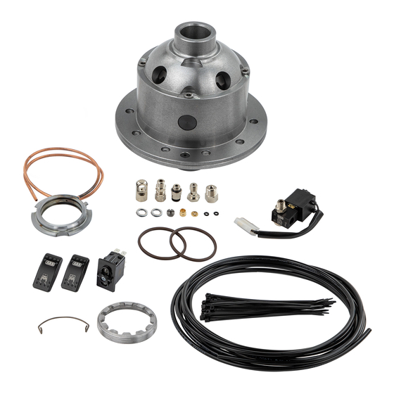
- Page 1 RD128 LAND ROVER, 24 SPLINE, BANJO AIR OPERATED LOCKING DIFFERENTIAL INSTALLATION GUIDE...
- Page 2 No liability is assumed for damages resulting in the use of the information contained herein. ARB AIR LOCKER Locking Differentials and AIR LOCKER are trademarks of ARB Corporation Limited. Other product names used herein are for identification purposes only and may be trademarks of their respective owners.
-
Page 3: Table Of Contents
Table of Contents: 1 Introduction 1.1 Pre-Installation Preparation 1.2 Tool-Kit Recommendations 2 Removing the Existing Differential 2.1 Vehicle Support 2.2 Differential Fluid Drain 2.3 Removing of the Axles and Differential 2.4 Marking the Bearing Caps 2.5 Checking the Current Backlash Amount 2.6 Removing the Differential Carrier 3 Installing the Air Locker 3.1 Mounting the Ring Gear... -
Page 5: Introduction
Although your ARB Air Locker comes complete with all the step by step instructions you will need to supplement your vehicle manufacturer’s service manual and install your new differential, ARB recommends that you have your Air Locker installed by a trained professional. -
Page 6: Tool-Kit Recommendations
A gasket sealant or replacement gasket for your third member. A sufficient volume of differential oil to completely refill your housing. (See the ARB Air Locker Operating and Service Manual for recommended lubricants) A soap and water mixture to test for air leaks. -
Page 7: Removing The Existing Differential
Any misalignment of the axle tubes may result in excessive wear and/or failure of your differential and axle shafts. ARB strongly recommends that you have your axle assembly inspected for concentricity and straightness before... -
Page 8: Marking The Bearing Caps
2 Removing the Existing Differential Marking the Bearing Caps Using a small pointed center punch, gently mark the bearing caps in a way that will enable you to know which cap is ‘LEFT’ and which cap is ‘RIGHT’, which way is ‘UP’ and which way is ‘DOWN’. (Fig.1.) ... -
Page 9: Checking The Current Backlash Amount
2 Removing the Existing Differential Checking the Current Backlash Amount IMPORTANT: This step is a precautionary measure recommended by ARB due to the fact that some after market ring and pinion sets have been manufactured to run with different backlash settings than those specified by your vehicle manufacturer. -
Page 10: Removing The Differential Carrier
2 Removing the Existing Differential Removing the differential carrier Remove the adjuster nut locking tabs. Remove the bearing caps from the third member. Remove the adjuster nuts. Carefully remove the differential carrier from the third member. ... -
Page 11: Installing The Air Locker
3 Installing the Air Locker Mounting the Ring Gear Remove the bolts that hold the ring gear in place. Using a plastic or copper hammer, tap in a circle around the ring gear to separate it from the differential carrier. ... -
Page 12: Installing The Carrier Bearings
3 Installing the Air Locker Figure 4. Installing the Carrier Bearings Apply a thin film of high pressure grease to the bearing journals of the Air Locker, then press the bearing cones onto the bearing journals as shown in figure 5. Figure 5. -
Page 13: Drilling And Tapping The Bulkhead Port
3 Installing the Air Locker Drilling and Tapping the Bulkhead Port An air line port must be drilled and tapped through the differential housing to mount the bulkhead fitting into. Mark a spot on the left hand side (opposite the ring gear) toward the top of the differential housing that is in an area well clear of the differential, the ring gear, and any other obstructions that could snag the seal housing tube. -
Page 14: Final Air Locker Assembly
3 Installing the Air Locker Final Air Locker Assembly Clean all parts of the differential assembly, paying particular attention to the seal housing journal. Place the Air Locker into the differential housing and install the bearing caps. NOTE : Be sure to check that the bearing caps are on the correct sides of the third member and are correctly aligned. - Page 15 3 Installing the Air Locker CLEARANCE REQUIRED Figure 7. Insert the original adjuster nut onto the opposite side of the differential and tighten with the appropriate adjuster nut wrench. NOTE : You should now feel some backlash between the ring and pinion gears.
-
Page 16: Checking The Backlash
3 Installing the Air Locker Checking the Backlash Set a depth indicator on one of the ring gear teeth (Fig.8.). While supporting the pinion gear by holding the drive shaft flange, rotate the differential in both directions while observing the maximum variation in depth from the indicator (i.e., the highest value minus the lowest value). -
Page 17: Installing The Seal Housing
3 Installing the Air Locker Installing the Seal Housing Make sure the grooves and airway of the seal housing are clean and free from any contaminants (e.g. water, dirt, metal filings, etc.). Inspect the seal housing O-rings (supplied) for dirt, damage or other conditions which might cause leaks. - Page 18 3 Installing the Air Locker Roll Pin Type 3.6.1 If your diff has roll pins instead of locking tabs, slightly rotate the adjuster nut so that the roll pin is in the center of one of the adjuster nut teeth as shown. When installing the roll pin, knock it down making sure that it will not contact the seal housing (Fig.
-
Page 19: Setting Up The Bulkhead Fitting
3 Installing the Air Locker Install the spring clip by first hooking both ends of the clip into the small aligned cutouts of the seal housing and the adjuster nut, and then snapping the clip into the groove of the seal housing using a screwdriver. - Page 20 3 Installing the Air Locker NOTE : Use an automotive brake line tubing cutter to cut the seal housing tube, never a hacksaw as this will leave metal filings in the air system. Figure 13. From the inside of the housing, insert the trimmed tube into the bulkhead.
- Page 21 3 Installing the Air Locker Figure 14. NOTE : Excessive tightening of the center compression nut is not necessary to form a good seal around the tube and may damage the O-ring, the seal housing tube, or the threads of the compression nut. NOTE : Make sure the seal housing tube is all of the way into the center compression nut while you are tightening...
-
Page 22: Profiling The Seal Housing Tube
3 Installing the Air Locker Profiling the Seal Housing Tube With the seal housing tube now firmly secured into the bulkhead fitting, bend the tube so that it closely follows the profile of the differential. (Figs.15.,16.,17. & 18.) Check that the contour of the tube will not allow the tube to come in contact with the bearing caps, the Air Locker, the ring gear, or any part of the inside of the axle housing. - Page 23 3 Installing the Air Locker Figure 17. Figure 18. IMPORTANT: In order for the seal housing to float and self center on the bearing journal, the seal housing tube must not be pulling against the seal housing. To check this, rotate the drive flange back and forth while observing the seal housing movement.
-
Page 24: Bench Testing The Air Locker
NOTE : An accurate way to test for air leaks is to fit a shut-off valve to an air pressure gauge (Available as ARB part #ALTG01). Charge with shop air until 620 KPA [90 PSI] is reached, shut the valve off, disconnect the air hose, and watch to see if there is any drop in pressure. -
Page 25: Reinstalling The Differential & Axles
3 Installing the Air Locker Reinstalling Differential and Axles 3.10 Reinstall the third member to the differential housing according to your vehicle service manual. Reinstall the drive shaft. Replace any damaged axle seals. Insert both axles fully into the housing, engaging splines, and then gently tap them inward. -
Page 26: Installing The Air System
4 Installing the Air System Mounting the Solenoid Connection to an ARB Air Compressor (Fig.20.) 4.1.1 Remove one of the 1/8” BSP plugs from its port in the compressor tank. Apply Teflon paste to the nipple (1/8” X 1/8” BSP) and insert it into the port and tighten. - Page 27 For ease of installation, quality of air supply, and a high level of dependability from your Air Locker(s), ARB strongly recommends use of a genuine ARB Air Compressor, however, the Air Locker air system can be operated on any alternate air source that meets each of the following guidelines: ...
-
Page 28: Running & Securing The Air Line
4 Installing the Air System Running and Securing the Air Line The path taken by the air line from your air source (i.e., compressor) to your Air Locker is unique to your vehicle and the position of your air source. Plan ahead carefully when running the air line and always follow these guidelines: ... -
Page 29: Connection To The Bulkhead Fitting
4 Installing the Air System NOTE : To remove the air line from the push-in fitting; pull outward on the flange of the fitting, push the air line as far into the fitting as possible and hold, push inward on the flange, and then pull the air line free of the fitting. - Page 30 4 Installing the Air System Screw on the outer compression nut and tighten, while supporting the center compression nut with a 3/8” spanner. The airline is now attached to the center compression nut. NOTE : The outer compression nut will tighten against a stop. Over tightening will not create a better seal.
-
Page 31: Mounting & Connecting The Electrical System
Switch(es) should not be mounted where they will be exposed to water (e.g., in the lower section of an inner door panel). ARB recommends that you apply the Air Locker Warning Sticker (ARB part # 210101) within close visual proximity of the switch location. - Page 32 5 Mounting & Connecting the Electrical System Figure 22.
-
Page 33: Wiring The Actuator System
5.2.1 When wiring the Air Locker actuator switch(es) and solenoid(s) to an ARB Air Compressor, all connections can easily be set up directly from the supplied wiring loom. (Fig. 23.) NOTE : 180405 & 180409 model looms shown for reference only. - Page 34 5 Mounting & Connecting the Electrical System SWITCH TERMINAL IDENTIFICATION Figure 24. Connection to an Alternate Air Source 5 .2.2 When connecting the actuation switch to an alternate air source, the switch(es) should be wired according to figures 25. and 26. depending on whether one or two Air Lockers will be installed in the vehicle.
- Page 35 5 Mounting & Connecting the Electrical System Dual Air Locker System 5.2.2.2 If two Air Lockers are to be installed in the system, ARB recommends that the switches and solenoids be wired according to figure 26. For safety reasons, this configuration allows SOLENOID 2 to be actuated only if SOLENOID 1 is already on.
-
Page 36: Testing & Final Assembly
6 Testing & Final Assembly Leak Testing With the vehicle parked and the engine off, turn the compressor on and wait until the air system is fully charged. NOTE : With the Air Locker(s) disengaged, the air source (i.e., compressor) should not have to recharge over time. -
Page 37: Filling The Differential
Rotate the same wheel. The wheels should again rotate in opposite directions. Filling the Differential NOTE : Consult the ARB Air Locker Operating & Service Manual for recommendations on differential lubricant specifications. Refill the differential until level with the filler hole. -
Page 38: Post-Installation Check List
6 Testing & Final Assembly Post-Installation Check List Now that the Air Locker installation has been completed, ARB recommends that you take the time to complete the following check list just to insure that you haven’t missed any of the vital steps. -
Page 39: Parts List
7 Parts List Exploded Assembly Diagram (See itemized parts list overleaf) Figure 27. -
Page 40: Itemized Parts List
WARNING LABEL 210101 BUMPER STICKER 210102 OPERATING & SERVICE MANUAL 210200 INSTALLATION GUIDE 2102128 * Not illustrated in exploded view. ** Available only as complete 6 gear set Part No. 2102128 Revision 7/10/2013 Copyright © 2013 by ARB Corporation Limited...
Need help?
Do you have a question about the AIRLOCKER RD128 and is the answer not in the manual?
Questions and answers