Table of Contents

Related Manuals for Renz Mobi 360


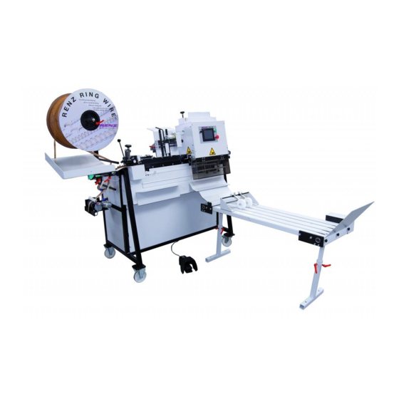
Summary of Contents for Renz Mobi 360
- Page 1 Operating instructions Mobi 360 (semi-automatic RingWire binding machine) Chr. RENZ GmbH Rechbergstr. 44 73540 Heubach Deutschland Phone: + 49 (0) 7173/186-0 Fax: + 49 (0) 7173/3720 mail@renz-germany.de www.renz.com www.renz-germany.de...
-
Page 2: Table Of Contents
Unpacking the machine......................11 Lifting points when transporting with industrial trucks............12 Space requirements and assembly ..................12 Electrical connections......................13 Start- up............................. 13 RENZ MOBI360 - technical data................14 Binding formats ........................14 Electrical connections......................14 Space requirement........................14 Site conditions .......................... 14 Weights............................ - Page 3 Table of contents MOBI360 page 3 10.8.4.1 Mounting the clamping into the lower position ...................25 10.8.4.2 Mounting the clamping into the upper position...................26 10.8.4.3 Warning about the T-bar..........................26 10.9 Entering display data........................ 27 10.9.1 Settings ................................27 10.9.2 Clamp settings on the display ........................28 10.9.3 Programming the counter..........................28 10.9.4...
-
Page 4: Ec Declaration Of Conformity
08/2011 was developed, designed and manufactured according to the above EC Directives exclusively by Company: Chr. Renz GmbH, Rechbergstraße 44, D-73540 Heubach The following harmonised standards were applied: EN ISO 12100, Safety of Machinery, Basic concepts, general principles for design EN 60204-1, Safety of Machinery, Electrical Equipment of Machines ................................ -
Page 5: As-Delivered Condition Of Your Mobi360
As-delivered condition of your MOBI360 page 5 MOBI360 As-delivered condition of your MOBI360 4036015 Machine number: Year of construction : Pitch (en): Voltage: Frequency : PLC- program : Display- program : Calendar hanger tool: no cal. hanger tool standard delivery device Delivery device: conveyor belt Additional accessories :... -
Page 6: Product Description
Product description Intended use The RENZ® MOBI360 binding machine is exclusively intended for binding with a wire comb. As an option, the wire comb elements can also be cut. The machine is not intended for applications other than those specified here... -
Page 7: General Safety Advice
General safety advice MOBI360 page 7 General safety advice Operator’s duty of care The MOBI360 binding machine has been designed and built according to carefully selected harmonised standards and additional technical specifications. It therefore meets the latest technical standards, offering the highest possible level of safety in operation. -
Page 8: Explanation Of Symbols
General safety advice MOBI360 page 8 Explanation of Symbols The symbols listed below appear in the operating instructions where appropriate, highlighting the specified residual risks. This symbol indicates a particular risk to personnel! (danger to life, risk of injury) Danger This symbol indicates a particular risk to the equipment, the material and / or the environment. -
Page 9: Safety Precautions During Normal Operation
General safety advice MOBI360 page 9 Safety precautions during normal operation The machine may only be operated by personnel who are authorised and trained in its use, who are conversant with the manual and can work according to the instructions laid down in it. Before switching on the machine, check and make sure that only authorised personnel are present in the working area around the machine and that nobody can be injured when the machine starts up. -
Page 10: Work On Electrical Equipment
General safety advice MOBI360 page 10 Work on electrical equipment Repair work on electrical equipment in the machine may only be carried out by a trained electrician. Examine electrical equipment regularly. Tighten loose connections immediately. Change damaged conductors / cables immediately. Always keep the switchgear cabinet closed. -
Page 11: Transport And Start-Up
Transport and start-up MOBI360 page 11 Transport and start-up Safety advice regarding transport To prevent damage to the machine and possible lethal injuries during transport, the following should be considered: Lifting devices and slinging equipment must meet the requirements of the regulations for the prevention of industrial accidents. -
Page 12: Lifting Points When Transporting With Industrial Trucks
Transport and start-up MOBI360 page 12 Lifting points when transporting with industrial trucks Place the forks of the stacker truck or pallet truck as wide apart as possible. Lift the machine in the centre, by its frame (see diagram on left). On steep slopes, do not use with lifting devices that have no brakes. -
Page 13: Electrical Connections
Transport and start-up MOBI360 page 13 Electrical connections The voltage is 230V (single phase) 50Hz [where required, 115V (single phase) 60Hz] The socket must be earthed. The socket must be equipped with a 16 Amp. fuse. If you are uncertain as to whether, or not the socket meets the specification, please consult an electrician before start-up. -
Page 14: Renz Mobi360 - Technical Data
RENZ MOBI360 - technical data MOBI360 page 14 RENZ MOBI360 - technical data Binding formats Bound side min. 50 mm - max. 360 mm Unbound side min. 90 mm Block thickness max. 27 mm 1/4" – 1 " RENZ RING WIRE... -
Page 15: Renz Ring Wire Table
RENZ RING WIRE ® Table MOBI360 page 15 ® RENZ RING WIRE Table recommended perforation cross section in mm max. book max. book min. max. loops / rectangular inch thickness thickness binding binding round hole inch hole w/o hanger with hanger... -
Page 16: Control Console And Switch
Control console and switch MOBI360 page 16 Control console and switch Touch screen surface The touch screen display is not only a display, but is also used for inputting machine and production data. Data that can be altered can be changed or deleted by touching the screen lightly in the relevant position. -
Page 17: Start Screen
Control console and switch MOBI360 page 17 9.1.1 Start screen A few seconds after switching on the MOBI360, the start screen appears. You can select the language, set the time , and change the contrast You progress onto the next screen by pressing the button 9.1.2 Settings All the data required to process a particular product can be... -
Page 18: Parameters
Control console and switch MOBI360 page 18 9.1.4 Parameters: In the parameter set up screen, the correction factors for the servo motors can be set. 9.1.5 Reference run: This is a pure information screen. It appears until all the servomotors and the knife have reached their start positions. Once the starting positions have been reached, the screen changes to Automatic or Cut mode (optional). -
Page 19: Setting Up The Mobi360
Setting up the MOBI360 MOBI360 page 19 10 Setting up the MOBI360 Changing the RING WIRE spool 10.1 The spring is under pressure. If you open the release handle the spring and the clamping device possibly jumps off the shaft. It could hurt you or your colleagues. -
Page 20: Cover For Small Sizes
Setting up the MOBI360 MOBI360 page 20 Cover for small sizes 10.3 To avoid problems during the paper transport into the binding unit with small sizes (smaller than 150mm) you must install a sheet metal cover. Information To install the cover please proceed as following: Switch off the Mobi360 (main switch into pos. -
Page 21: Changing The Feed Wheel (2:1 Or 3:1 Pitch)
Setting up the MOBI360 MOBI360 page 21 Changing the feed wheel (2:1 or 3:1 pitch) 10.5 To change the feed wheel please proceed as follows: Loosen the two screws on the dust cover and remove it. Loosen the three screws on the feed wheel . -
Page 22: Set Up Of The Feeding Section
Setting up the MOBI360 MOBI360 page 22 Set up of the feeding section 10.6 The MOBI360 can process RING WIRE combs from 1/4"to 1 ¼". However each diameter needs a special adjustment of the feeding section. Information To adjust the feeding section please proceed as follows. Turn the adjusting wheel as long as the two guiding rails... -
Page 23: Adjusting The Guide Slot On The Hanger Station
Setting up the MOBI360 MOBI360 page 23 Adjusting the guide slot on the hanger station 10.7 The cut RING WIRE elements are transported into the hanger station by a timing belt. The element is led into a gap between two rails . Depending on the diameter, different thicknesses of wire are used. -
Page 24: Adjusting The Rear Guide Rail
Setting up the MOBI360 MOBI360 page 24 10.8.2 Adjusting the rear guide rail Adjusting the hand wheel , until the indicator shows the desired diameter. 10.8.3 Adjusting the front guide rail Open the star knob screw on the left side opposed to the star know screw at the right side of the closing unit. -
Page 25: Adjusting The Clamping
Setting up the MOBI360 MOBI360 page 25 10.8.4 Adjusting the clamping Depending on the unbound height and the kind of paper you can use the upper or lower clamping position. Products smaller than 150mm only can be bound in the upper clamping position. -
Page 26: Mounting The Clamping Into The Upper Position
Setting up the MOBI360 MOBI360 page 26 10.8.4.2 Mounting the clamping into the upper position Open the screws that are fixing the clamping rail in the lower position and remove the rail. Put the rail from the inside to the mounting holes in the upper position . Fix the rail with the two screws . -
Page 27: Entering Display Data
Setting up the MOBI360 MOBI360 page 27 Entering display data 10.9 The touch-screen has a contact-sensitive surface. Lightly tapping the appropriate virtual switches triggers the relevant activity. Information Only use your fingers Do not operate the display with hard or pointed items, as they destroy the surface and thus the function of the display. -
Page 28: Clamp Settings On The Display
Setting up the MOBI360 MOBI360 page 28 The machine carries out a reference run, i.e. all axles are set to their start positions, after which the current configuration is set. If all drives are successfully referenced, the machine changes to the automatic screen. 10.9.2 Clamp settings on the display After a successful reference run the automatic screen is displayed. -
Page 29: Step By Step Mode
Setting up the MOBI360 MOBI360 page 29 10.9.5 Step by step mode In order to check the settings, it is advisable to produce the first item in step by step mode. Here the process is interrupted at certain points, allowing you to check your settings. Push the “automatic mode”... - Page 30 Setting up the MOBI360 MOBI360 page 30 When set to “clamp down”, the paper is deliberately bent by a special device. Because the block is effectively “shortened”, the stroke limiter must be set at around 1mm above the default value on the scale. Achtung The sketch on the right shows the principle of the special device that "bents"...
-
Page 31: Feed Test And Parameter Settings
Setting up the MOBI360 MOBI360 page 31 Feed test and parameter settings 10.10 10.10.1 Feed test If problems occur during the wire feeding-in process, such as too few, or too many rings, bent loops or a loop jam, you should check the loop feed using the “feed test”. -
Page 32: Parameter Settings
Setting up the MOBI360 MOBI360 page 32 10.10.2 Parameter settings Both the feed wheel and the timing belt are referenced to a zero point by sensors. Their subsequent movement away from the zero point depends on the values entered in the “parameter set up”... -
Page 33: Delivery Device
Setting up the MOBI360 MOBI360 page 33 Delivery device 10.11 10.11.1 Simple delivery device (standard) You can adjust the simple delivery device in the height and the inclination. To adjust the height please proceed as following: hold the upper part of the delivery device with one hand and open the release handle with the other. -
Page 34: Short Overview "Setting Up The Mobi360
Short overview "Setting up the MOBI360" MOBI360 page 34 11 Short overview "Setting up the MOBI360" Choose an applicable Ring Wire diameter according to your product. Use the table from chapter 8). Change the Ring Wire spool to the desired diameter (see chapter 10.1) and guide the separation paper like described in chapter 10.2. -
Page 35: Ka300(R) Hanger Dispenser
KA300(R) hanger dispenser MOBI360 page 35 12 KA300(R) hanger dispenser KA300 12.1 12.1.1 Installation KA300 If you ordered the KA300 together with your MOBI360 it will be fixed and adjusted by the factory. If you ordered it later you have to install and adjust it by yourself. Information To assemble the KA 300 hanger dispenser proceed as follows:... -
Page 36: Error Messages
Error messages MOBI360 page 36 13 Error messages Error messages on the display 13.1 13.1.1 Incorrect input When entering the number of loops, the value "0" may not be entered into the first field (far left). If the value "0" is entered, an error message appears. -
Page 37: Troubleshooting
Troubleshooting MOBI360 page 37 14 Troubleshooting Faults when drawing in loops 14.1 RING WIRE elements are paid off in an Check the angle of the inlet plate. The spool uncontrolled manner, or pass by the inlet plate. payoff motor stops as soon as the RING WIRE element moves above the orange proximity switch. -
Page 38: Faults In Transporting Of The Material To Be Bound Into The Closing Unit
Troubleshooting MOBI360 page 38 Faults in transporting of the material to be bound into the closing unit 14.2 The pusher on the transport belt is positioned Correct the “paper feed” parameter in the too far from the edge of the material to be display parameters - see 10.7.1. -
Page 39: Default Values And Factory Settings
Default values and factory settings page 39 MOBI360 15 Default values and factory settings Default in the settings display 15.1 RING WIRE diameter factory settings for closing 1/4" 5/16" 3/8" 7/16" 1/2" 9/16" 5/8" 3/4" 1" 1 1/8" 1 1/4" Values in the parameter display 15.2 factory settings... -
Page 40: Some Space For Your Notes
some space for your notes MOBI360 page 40 16 some space for your notes... - Page 41 some space for your notes MOBI360 page 41...
- Page 42 some space for your notes MOBI360 page 42...
Need help?
Do you have a question about the Mobi 360 and is the answer not in the manual?
Questions and answers