
Related Manuals for TGS DAISY Series


Summary of Contents for TGS DAISY Series
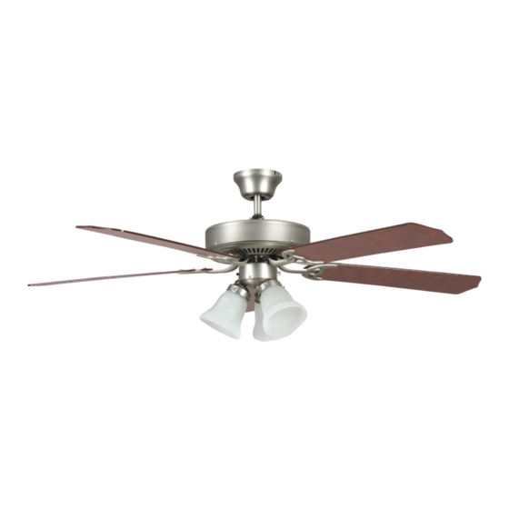
- Page 1 DAISY™ INSTALLATION INSTRUCTIONS 52-INCH INDOOR LED CEILING FAN www.trulygreensolutions.com...
- Page 2 Dimension Reference: 5-1/4 in 52 in Hardware Package Included: Hardware Package Paper Washers Bracket Screw S11. Fan Parts Included: 3. Canopy 4. Coupler Cover 5. Fan Motor Assembly 7. Glass Bulb Blade Arm 10. Fan Blade www.trulygreensolutions.com...
-
Page 3: Exploded View
Exploded View: Canopy Screws Mounting Bracket Support Rod Ceiling Canopy Coupler Cover Cotter Pin Safety Pin Motor Coupler Blade Arm Screws Fiber Washer Fan Motor Assembly Three Speed Switch Pull Chain Blade Blade Arm Switch Housing Glass Bulb Light Switch Pull Chain www.trulygreensolutions.com... -
Page 4: Safety Instructions
Safety Instructions: READ ALL SAFETY INFORMATION AND INSTALLATION INSTRUCTIONS BEFORE YOU BEGIN INSTALLING THE FAN. IF YOU ARE NOT FAMILIAR WITH NATIONAL AND LOCAL ELECTRICAL CODES AND BASIC ELECTRICAL WIRING PROCEDURES WE RECOMMEND THAT YOU HAVE A QUALIFIED ELECTRICIAN INSTALL YOUR NEW CEILING FAN. SAVE INSTRUCTIONS. •... -
Page 5: Installation Instructions
Warning: • To reduce the risk of fire, electrical shock, or personal injury, mount this fan to an outlet box marked “Acceptable for Fan Support of 22.7 kg ( 50 lbs )” or less and use Mounting Screws provided with the outlet box. - Page 6 FIG 2 Slotted Screw Step 2 Install Mounting Bracket Mounting Bracket Remove the two non-slotted mounting screws on the top of the canopy. Back the two slotted screws out about half way. This will enable you to Non-Slotted remove the mounting bracket from canopy (see figure 2). Screw Canopy FIG 3...
- Page 7 FIG 7 Step 3 Hanging the Fan Body (continued...) Trim the lead wires, leaving about six inches of each wire extending from the Ground Wire support rod (see figure 7). Ball Hanger Support Rod Step 4 Making the Electrical Connections FIG 8-1 To operate your ceiling fan with the pull chain(s) and switches mounted on your fan, follow the instruction below (see figure 8-1).
-
Page 8: Maintenance
FIG 10 Step 6 Blade And Blade Arm Assembly Lightly attach each blade to the blade arm by using 3pcs Motor Housing screws and fiber washers as shown in figure 10. Tighten each screw. Make sure the blade is straight. Fiber Washer Fan Blade Screw Attach each blade assembly to motor aeembly by using 2pcs... -
Page 9: Operation
Operation: The pull chain located on the switch housing controls the speed of your fan. When the fan is OFF, pull the chain once for HIGH speed, twice for MEDIUM speed, three times for LOW speed and a fourth time to turn it off again. Turn fan completely off before moving the reverse switch. -
Page 10: Troubleshooting Guide
Troubleshooting Guide: cases these installation errors may be mistaken for defects. If you experience any faults please check this troubleshooting guide. Problem Suggested Remedy: 1. Check main and branch circuit fuses or circuit breakers. 2. Check line wire connections to fan and switch wire connections in switch housing. CAUTION: 1.
Need help?
Do you have a question about the DAISY Series and is the answer not in the manual?
Questions and answers