
Related Manuals for TGS AVIO Series


Summary of Contents for TGS AVIO Series
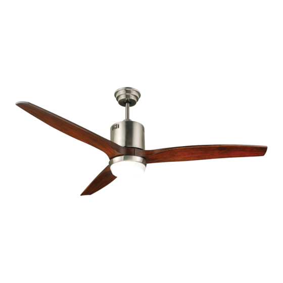
- Page 1 AVIO™ INSTALLATION INSTRUCTIONS 52-INCH INDOOR LED CEILING FAN/ 3 Blades/ Light Kit www.trulygreensolutions.com...
- Page 2 Dimension Reference: 5-1/2 inch 52 inch Hardware Package Included: Hardware Package S1. Machine Screws S2. Machine Screws S3. Wood Screws S4. Washers S5. Lock Washers S6. Star Washers S7. Wire Nuts Blade Screws & Washers Rubber Washers S10. Balance Kit Rubber Ring Fan Parts Included: 3.
-
Page 3: Exploded View
Exploded View: Mounting Bracket Mounting Bracket screw Support Rod Ceiling Canopy Canopy Screws Safety Pin Coupler Cover Cotter Pin Fan Motor Blade Assembly Black Wire Blade Screw White Wire Light Kit Black Wire White Wire LED Module Glass Shade www.trulygreensolutions.com... -
Page 4: Safety Instructions
Safety Instructions: READ ALL SAFETY INFORMATION AND INSTALLATION INSTRUCTIONS BEFORE YOU BEGIN INSTALLING THE FAN. IF YOU ARE NOT FAMILIAR WITH NATIONAL AND LOCAL ELECTRICAL CODES AND BASIC ELECTRICAL WIRING PROCEDURES WE RECOMMEND THAT YOU HAVE A QUALIFIED ELECTRICIAN INSTALL YOUR NEW CEILING FAN. SAVE INSTRUCTIONS. •... -
Page 5: Installation Instructions
Warning: • To reduce the risk of fire, electrical shock, or personal injury, mount this fan to an outlet box marked “Acceptable for Fan Support of 22.7 kg ( 50 lbs )” or less and use Mounting Screws provided with the outlet box. CAUTION: Install the primary mounting means and use only the hardware provided with the fan. - Page 6 Step 2 Install Mounting Bracket FIG 3 Loosen the two canopy mounting screws on the downside face of the mounting bracket. Back them out about half way. This will allow for easier installation of the ceiling canopy later (see figure 3). Ceiling Canopy Mounting Screw FIG 4 Junction Box...
- Page 7 FIG 9 Mounting Bracket Step 4 Hanging the Fan Body Keyway Pin Notice the half ball on the end of the support rod is grooved down one side (see Ball Hanger figure 9). This keyway fits over the small keyway pin on the inside of the mounting bracket and keeps the ceiling fan from spinning on the mounting bracket.
-
Page 8: Maintenance
FIG 13 Step 6 Secure Canopy Slide the ceiling canopy up into place over the ceiling mounting bracket. Secure the ceiling canopy onto the mounting bracket using canopy mounting screws and washers.(see figure 13). FIG 14 Step 7 Installation of Lighting Fixture Place the light mounting plate onto fan. - Page 9 Remote Control Operation Instruction (see drawing below for the following instructions) The Remote Control Transmitter NOTE: The Remote Control Transmitter comes Transmitter with a bracket that can be mounted in any con- venient place you choose. Next to a light switch in the same room as the ceiling fan is a good place.
- Page 10 Wall Control Operation Instruction (see drawing below for following instructions) IMPORTANT: READ THESE INSTRUCTIONS CAREFULLY BEFORE ATTEMPTING TO INSTALL THIS ELECTRICALDEVICE. TO AVOID POSSIBLE ELECTRICAL SHOCK,BE SURE THE ELECTRICITY IS TURNED OFF AT THE CIRCUIT BREAKER PANEL OR FUSE BOX BEFORE WIRING. TO AVOID THE RISK OF FIRE,ELECTRICAL SHOCK AND SERIOUS PERSONAL INJURY,PLEASE FOLLOW THESE INSTRUCTIONS.
- Page 11 Fig. 3 Wall Control Wall Control Wall Control Connect the black wire from the junction box to the fixture with the slide bars on the wall control. black AC IN. You have four (4) speeds plus OFF, and, when you push the Connect the blue wire from the fan to the blue wire knob upward slowly, the lightness of light will turn brigther from the control.
-
Page 12: Operation
Operation: The pull chain located on the switch housing controls the speed of your fan. When the fan is OFF, pull the chain once for HIGH speed, twice for MEDIUM speed, three times for LOW speed and a fourth time to turn it off again. Turn fan completely off before moving the reverse switch. -
Page 13: Troubleshooting Guide
Troubleshooting Guide: cases these installation errors may be mistaken for defects. If you experience any faults please check this troubleshooting guide. Problem Suggested Remedy: 1. Check main and branch circuit fuses or circuit breakers. 2. Check line wire connections to fan and switch wire connections in switch housing. CAUTION: 1.
Need help?
Do you have a question about the AVIO Series and is the answer not in the manual?
Questions and answers