Table of Contents
Advertisement
Quick Links
Advertisement
Table of Contents

Related Manuals for Packo HP Series

Summary of Contents for Packo HP Series
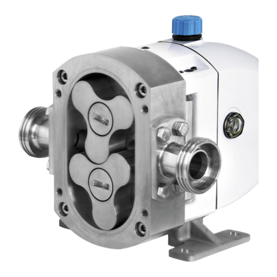
- Page 1 Hygienic rotary lobe pumps...
-
Page 2: Table Of Contents
CONTENTS INTRODUCTION General Information Manufacturer Copyright Declaration of conformity Principle of operation Intended Use Type designation Sound pressure level SAFETY INSTALLATION Unpacking and lifting of the pump Operating limitations Location & orientation Drives Baseplate Guards and safety Electrical connection of the motor Ports and pipework Enlarged rectangular inlet 3.10... -
Page 3: Introduction
PACKO INOX LTD has the copyright on this document. These operating instructions may be reproduced in full in the operating instructions of the machine or installation in which the pump is installed and may be used for training personnel who must work on or with the pump. -
Page 4: Declaration Of Conformity
15-26, Beodeul-ro 1362, Paltan-myeon, Hwaseong-si, Gyeonggi-do, 18578, Rep. of Korea confirm that the Packo pump type ……........, with serial number ........fully complies with the Directive Machinery and with the (harmonised) standard EN 809, ENISO12100. It must be brought to your attention that our product is intended to be built into a machine, and that, on the basis of the “Machinery”... -
Page 5: Principle Of Operation
1.5 PRINCIPLE OF OPERATION are completely fitted and functional. If any areas are subject to have the risk of HP & LH pumps have 2 rotors which turn in explosion, the relevant explosion-proof designed opposite directions. Fluid enters the pump from pumps should be used. -
Page 6: Sound Pressure Level
4: number of poles of the motor Mat. Code: (TLHP-95) D37SSVQ TLHP: Rotor code (TLHE = tri-lobe high efficiency, TLHP = tri-lobe high pressure, SCHE = scimitar high efficiency, SCHP = scimitar high pressure) 95: temperature class of the pump (Deg. C) ... -
Page 7: Safety
2 SAFETY Throughout this manual your attention is drawn to certain procedures which must be followed to ensure safe operation and servicing of this product. ATTENTION Do not ignore safety instructions. ATTENTION Do not remove by-pass or tamper with safety devices. -
Page 8: Installation
3.2 OPERATING LIMITATIONS 3 INSTALLATION PRIMING: HP & LH pumps are not truly self- Careful attention to correct installation of HP & LH priming and should be installed in a “flooded inlet” pumps, and recognition of certain limitations to pipe arrangement i.e. with the pump lower than the operating conditions of the pump, will ensure the level of liquid to be pumped and with the long life and trouble-free running. - Page 9 • In a clear area allowing access all around • Fit foot bolts (21) (Supplied in foot kit) pump and drive for easy servicing. through the feet into the bearing housing • With space above for lifting equipment (1) and tighten to torque specified in required.
- Page 10 foot location recess and place in a safe Vertical Ports Left Shaft Drive location (33 & 34) (When viewed from front) • Push the foot dowel pin (32) (supplied in the foot kit) into the un-tapped hole in the bottom left foot location recess. •...
-
Page 11: Drives
• Fit the foot bolts (21) (Supplied in the foot against overload. kit) through the feet into the bearing In all cases the coupling manufacturer’s limits housing (1) and tighten to the torque should be adhered to. specified in Table 1. See performance curve to calculate torque. -
Page 12: Electrical Connection Of The Motor
Local safety regulations and codes of practice will installed in the terminal box. Do not connect the specify the minimum acceptable standard but as motor if you have any doubts regarding the a guide: interpretation of the connection diagram. If in doubt please contact JEC. -
Page 13: Ports And Pipework
3.8 PORTS AND PIPEWORK • Fit expansion joints if necessary to prevent thermal expansion forces being transmitted to the pump. To add or change any pump ports the correct • Ensure all pipe joints are: port kit needs to be applied. Port kits contain all o Air-tight under vacuum;... -
Page 14: Seals And Flushing
sophisticated seal type. (Figure 9) Figure 7 - Pump head - thermal jacket Can be used in conjunction with end cover relief Figure 9 - Single mechanical seal (Size 4-8) valve. Note that silicon carbide-on-silicon carbide, seals End Cover – Thermal Jacket recommended steam-purged applications as the seal faces can bind together... - Page 15 • Pumped fluid changes state in contact with air, i.e. crystallizes, forms a film, dries out or precipitates solids. The flush dissolves and rinses away the small amount of residue which could build up on the edges of the seal faces. •...
- Page 16 full pressure within the pumped fluid pipe system. No bacteria or contamination can be allowed to enter the pump, i.e. an aseptic system. Double Mechanical Seal with high A steam barrier system must be installed as pressure liquid flush when: follows: •...
-
Page 17: Seal Materials
available for nonabrasive and lubricating fluids. All secondary double mechanical seals are with carbon on silicon carbide faces. ELASTOMERS Product contacting primary elastomers must be selected to be compatible with the product and the process operation. Consideration must given chemical compatibility, temperatures material... -
Page 18: Lubrication
3.14 LUBRICATION • MAKE SURE THAT MAXIMUM PRESSURE PUMP Packo HP & LH pumps have oil lubricated shaft EXCEEDED. CHECK THE NAMEPLATE. bearings and timing gears. • Start unscrewing the adjusting screw (135) counter-clockwise until pressure gauge reading starts to drop. -
Page 19: Start Up & Routine Checks
HP/32 & 34 0,38 liter HP/42 & 44 0,66 liter HP/52 & 54 1,17 liter HP/62 & 64 2,20 liter LH/72, 74 & 76 5,50 liter 4 START UP & ROUTINE CHECKS 4.1 START UP Figure 16 - Direction of rotation - viewed from pump Before starting the pump for the first time or after head (Principle applies to all mounting orientations) servicing... -
Page 20: Daily Checks
when 110°C (230°F) may be reached. and signs of wear. • If operating at high speeds or with hot • Inspect the seal faces for wear and the liquids, the surface of the pump can condition of the elastomers. Replace if become hot. -
Page 21: Cleaning In Place (Cip) & Manual Cleaning
or loss. manufacturer’s recommended dilution, temperature and circulation time but do In order to clean the pump it must either be exceed 90°C (195°F). Confirm dismantled (manual cleaning), or cleaned in place compatibility with pump materials of (CIP) as part of the procedure for cleaning the construction. -
Page 22: Sterilizing In Place (Sip)
Take care not to scratch or damage pump parts. • Pass clean, wet steam through the system One part of the seal faces remains in the rotor until all component temperatures have when it is removed. Be extremely careful not to stabilized. -
Page 23: Inspection And Repair
bind together. Proceed as follows: • At the end of the hold time, the pump must be allowed to cool naturally or can ATTENTION be purged with sterile air/inert gas. The end cover is heavy; take care to support it when removing the bolts (123). -
Page 24: Primary Seals
Figure 18 - Loosen the rotor bolt (bottom rotor) HP 52/54 Rotor Screw 55Nm HP 62/64 Rotor Screw 100Nm • Use only the special tool (181) supplied to LH 72/74/76 Hygienic Cap 40Nm loosen and retighten. Both screws have a (tri-bolt) Bolts 50Nm... - Page 25 HP32 & HP34 Pumps ATTENTION Note: Double mechanical shaft seals are not available on the HP3 size pumps • Pull the static faces (80) from their bores in the rotor case (51), removing the joint ring (83) with each seal face. Take care not to scratch or damage the smooth face of the seal.
- Page 26 6.7 ROTOR CASE), static seal seats should be Note: if refitting previously used seal faces inserted into the rotor case, before mounting on ensure that rotary and static faces are in their to bearing housing. original pairs. • To fit the seal seat to the rotor (56), first HP4-6 insert L cup rubber (83) into the rotor (DO NOT lubricate), ensure alignment with the...
-
Page 27: Mechanical Shaft Seals - Single Flushed
• Check the coil springs are in place in the seal 6.4 MECHANICAL SHAFT SEALS - housings. SINGLE FLUSHED • Fit the Quad ring (83) to the seal face and lubricate the bore in the seal housings with a Pumps fitted with flushed seals have lip seals suitable lubricant compatible with the pumped fitted in order to retain a flushing or barrier fluid. -
Page 28: Secondary Mechanical Seals - Double
Seals. To service secondary seals it is necessary to remove the rotor case (6.7 ROTOR CASE). Note: Not available on HP32 and HP34 pumps. Figure 27 - Single flushed mechanical seal Re-Fitting HP3: • Push the new lip seals into the seal housings. •... -
Page 29: Seal Housings
• Fit the soft washer (92a) in place on the plate (81). Ensure that the 3 slots on the support ring. outer edge of the drive plate locate on the 3 • Fit the O-ring (93) to the rotary seal seat (92). pins in the housing. -
Page 30: Rotor Clearance - Checking And Adjustment
are removed. If primary or secondary static seal seats (80) are still fitted to the rotor case take care not to damage them on the shaft ends (24 & 25). If single flushed seals are fitted take care not to damage them on the shaft splines or shims (30). - Page 31 • Measure the thickness of the shim pack for Front: Radial: each shaft and calculate the thickness of the rotor to rotor to shim to add or remove on each shaft to give Pump Rotor front rotor Mesh: Mesh: model code cover case...
-
Page 32: End Cover Relief Valve
AND PRE-LOAD) setup columns in Table 6. • Align the rotors in the rotor case as per Figure • If the values are not within the limits remove the rotors and re-fit using the procedure • Check the rotor to rotor meshing clearance (d stated in the section For Re-fitting or New in Figure 30, left of bottom lobe) on the first Rotors. -
Page 33: Thermal Jacket - End Cover
the seat onto the end cover with the O-ring towards the end cover i.e. the conical face • Dismantle the jacket (144) from the cover uppermost. (143) by removing the screw (147) from the Position the 2 screw holes in the valve seat centre of the jacket over the corresponding threaded holes in the •... -
Page 34: Gearbox Shafts, Gears And Bearings
Preliminary inspection can now be carried out The inner race of the rear bearing (4) will slide off without further dismantling; i.e. condition of the shaft. Be careful that it does not fall off. timing gears or movement in the bearings. Alternatively, prize out the front lip seals (23) first •... - Page 35 be attached to the front of the shafts so a plastic block can be placed between them as if you were tightening the rotor screws. Alternatively a plastic block can be inserted between the gears to stop the rotors turning. For all HP3, HP7 and HP8 sized pumps do not fit Figure 34 - Inner-ring fitment the gear drive key (28), gear (6), tab washer (7)
-
Page 36: Atex Applications
ATEX APPLICATIONS ATTENTION Do not fit gear (6) on HP3 and LH7 models. General Note: For HP3 and LH7 models. This supplement applies to the HP & LH Rotary Lobe Pumps used in applications covered by the • Once bearing nuts are to the correct torque in ATEX Directive 2014/34/EC. - Page 37 Seal Flushing To prevent the potential risk of hot surfaces on the pump seals it is essential to apply additional cooling and lubrication of the seal faces through the use on an additional auxiliary support system as described 3.11 SEALS AND FLUSHING. In addition to the system requirements described in 3.11 SEALS AND FLUSHING, controls must be implemented to ensure the continuous and...
-
Page 38: Exploded Diagrams
8 EXPLODED DIAGRAMS 8.1 HP & LH Exploded Diagram Data sheets highlighting the parts lists are available on request. -
Page 39: Hp 3 Size Exploded Diagram
HP 3 Size Exploded Diagram Data sheets highlighting the parts lists are available on request. -
Page 40: Options & Extras - Sectional Views
Options & Extras - Sectional Views HP & LH Single Mechanical Seal HP 3 Size Single Mechanical Seal HP & LH Flushed Mechanical Seal HP 3 Size Flushed Mechanical Seal HP & LH Double Mechanical Seal HP 4 and 5 size Packed Gland Seal... - Page 41 HP & LH End Cover Relief Valve HP & LH Thermal Jacket – Pump Head HP & LH Thermal Jacket – End Cover...
- Page 42 Ref. 259706...
Need help?
Do you have a question about the HP Series and is the answer not in the manual?
Questions and answers