
Related Manuals for All-Flo A101


Summary of Contents for All-Flo A101
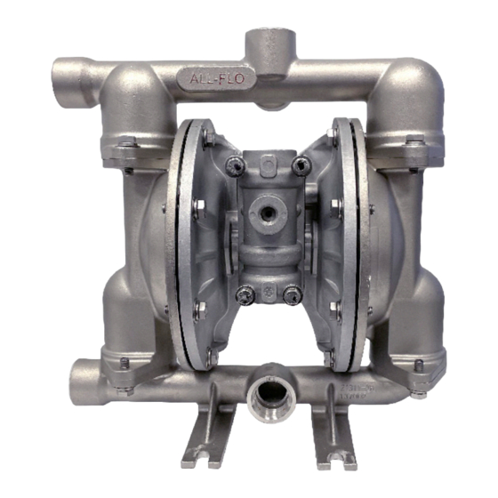
- Page 1 INSTALLATION OPERATION & MAINTENANCE A101 METAL 1 INCH AIR-OPERATED DOUBLE-DIAPHRAGM PUMP WE PUMP SOLUTIONS WE PUMP SOLUTIONS ® ®...
-
Page 2: Table Of Contents
SECTION 7 REPAIR AND ASSEMBLY PUMP WET END REMOVAL ..........13-14 AIR VALVE REMOVAL ............15-16 PILOT VALVE REMOVAL ............17-18 TORQUE SPECIFICATIONS ............18 SECTION 8 EXPLODED VIEWS AND PARTS LISTS 19-21 SECTION 9 ELASTOMERS SECTION 10 WARRANTY AND REGISTRATION ALF-12080-E-02 All-Flo... - Page 3 Always use minimum air pressure when pumping at elevated temperatures. CAUTION It is the end user’s responsibility to maintain the process fluid’s temperature during use. CAUTION Ensure all wetted components are chemically compatible with the process fluid and the cleaning fluid. ALF-12080-E-02 All-Flo...
- Page 4 SECTION NOTES: ALF-12080-E-02 All-Flo...
- Page 5 AIR END REPAIR KIT consist of diaphragms, (back-up diaphragms if required), balls, Air end repair kit contains pilot seats and seat O-rings. sleeve assembly and main air valve. See matrix below. AIR SECTION A = Aluminum Bold indicates recommended options ALF-12080-E-02 All-Flo...
- Page 6 The process of alternating right suction / left discharge (and vice-versa) continues as long as compressed air is supplied to the pump. ALF-12080-E-02 All-Flo...
- Page 7 SECTION 1” PUMP DIMENSIONS STAINLESS STEEL *Note - Suction Center Front / Discharge Center Rear are default ports. See part number matrix option code for additional porting options. **Note - Standard Muffler Shown ALF-12080-E-02 All-Flo...
-
Page 8: Performance Curves
*Flow rates indicated on all three charts shown were determined by pumping water at flooded suction. For optimum life and performance, pumps should be specified so that daily operation parameters will fall in the center of the pump performance curve. ALF-12080-E-02 All-Flo... -
Page 9: Installation, Troubleshooting And Maintenance
LOCATION Ensure that the pump is installed in an accessible location, in order to facilitate future service and maintenance. ALF-12080-E-02 All-Flo... - Page 10 SUGGESTED INSTALLATION This illustration is a generic representation of an air operated double-diaphragm pump. ALF-12080-E-02 All-Flo...
-
Page 11: Troubleshooting
Pump may be cavitating, reduce speed of operation Suction strainer clogged Pump Will Not Prime Air leak in suction pipe Air leak in pump manifold connections Suction strainer and lines clogged Excessive lift conditions Check valve wear Debris in check valve ALF-12080-E-02 All-Flo... -
Page 12: Operation
Suction strainers may be employed to reduce or eliminate larger solids, but Schedule pump service based on pump’s service routine maintenance is necessary in order to prevent history. a restriction on the suction. ALF-12080-E-02 All-Flo... -
Page 13: Repair And Assembly
Using the 1/2 inch wrench remove Remove the “Suction Manifold”. Remove the “O-Ring”, “Valve four “Hex-Head Cap Screws Seat” and “Ball” from the “Outer (5/16”-18 x 1”)", and four “Flat and Chamber”. Lock Washers (5/16”)” from the “Suction Manifold”. ALF-12080-E-02 All-Flo... - Page 14 To assemble the wet end of the pump, reverse the order of disassembly. Ensure all hardware is fastened in accordance with torque specifications (see page 18). Inverting one of the diaphragms during reassembly will facilitate ease of assembly. ALF-12080-E-02 All-Flo...
-
Page 15: Air Valve Removal
“Air-Valve Assembly”. main “Air-Valve Assembly”. the “Air Valve End Plug” from the main “Air-Valve Assembly”. Note: The smooth shinny side of the shuttle plate should be toward Ensure the “O-Ring” is installed the shuttle car. when reassembling. ALF-12080-E-02 All-Flo... - Page 16 Note that if the lip-seals are installed incorrectly, they will be unable to rotate. Insert the spool, the spool’s shorter piston is to be on the plug side, ensure O-ring is enstalled, and then the air-valve end plug into position. ALF-12080-E-02 All-Flo...
-
Page 17: Pilot Valve Removal
Remove the “Pilot Sleeve” from (Pilot Sleeve)” and four “O-Rings disassemble the “Diaphragm Rod the disassembled “Diaphragm (Pilot Sleeve)” from the pilot Assembly” into its two parts. Rod Assembly”. sleeve assembly. Note they are installed with thread locker. ALF-12080-E-02 All-Flo... -
Page 18: Torque Specifications
Wrench Size Manifold Bolts 90 in-lbs (10.2 N-m) 1/2” Chamber Bolts 60 in-lbs (6.8 N-m 1/2” Air Valve Bolts 40 in-lbs (4.5 N-m) 7/16” Diaphragm plate 90 in-lbs (10.2 N-m) 3/4” Diaphragm plate (PTFE) 90 in-lbs (10.2 N-m) 3/4” ALF-12080-E-02 All-Flo... -
Page 19: Exploded Views And Parts Lists
SECTION EXPLODED VIEW & PARTS LIST A101-*A*-****-*** STAINLESS STEEL ALF-12080-E-02 All-Flo... - Page 20 PARTS LIST - STAINLESS STEEL A101-*A*-****-*** ITEM DESCRIPTION QTY PUMP MODEL PART NO. MATERIAL DISCHARGE MANIFOLD A101-NA3-****-*** 11330-26-NPT Stainless Steel A101-BA3-****-*** 11330-26-BSPT Stainless Steel BALL A101-*A*-*V**-*** 11008-13 † A101-*A*-*E**-*** 11008-15 † EPDM A101-*A*-*G**-*** 11008-19 † Bunalast A101-*A*-*N**-*** 11008-21 † Buna-N A101-*A*-*S**-*** 11008-23 †...
- Page 21 PARTS LIST - ALUMINUM & STAINLESS STEEL A101-*A*-****-*** ITEM DESCRIPTION PUMP MODEL PART NO. MATERIAL AIR VALVE END PLUG ALL MODELS 11706-20 Aluminum ‡ MUFFLER ALL MODELS 13001-00 Standard MUFFLER (METAL) OPTIONAL 13009-00 Metal PIPE PLUG A101-NA3-****-*** 12265-26-NPT Stainless Steel...
- Page 22 Bunalast is a trademark of PSG-Californa. Santoprene is a registered trademark of ExxonMobil Chemical Co. ® Hytrel is a registered trademark of DuPont Performance Elastomers L.L.C. ® Magnalube is a registered trademark of Carleton-Stuart Corp. ® ALF-12080-E-02 All-Flo...
- Page 23 IMPLIED WARRANTY OF FITNESS FOR A PARTICULAR PURPOSE, AND ANY IMPLIED WARRANTIES OTHERWISE ARISING FROM A COURSE OF DEALING OR TRADE. All-Flo will not, in ANY event, be liable for any loss of profit, interruption of business or any other special, consequential or incidental damages suffered or sustained by Customer.
- Page 24 P: +1 (440) 354-1700 F: +1 (440) 354-9466 all-flo.com All-Flo is committed to the pursuit of designing and manufacturing the highest quality product available to industry. Since the beginning in 1986, All-Flo engineers have used their extensive knowledge of today’s...
Need help?
Do you have a question about the A101 and is the answer not in the manual?
Questions and answers