
Related Manuals for All-Flo A100


Summary of Contents for All-Flo A100
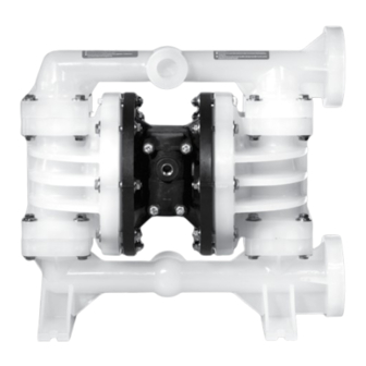
- Page 1 PUMP OPERATIONS & MAINTENANCE MANUAL A100 - PLASTIC 1 INCH AIR OPERATED DOUBLE DIAPHRAGM PUMP all-flo.com...
-
Page 2: Table Of Contents
SECTION 7 REPAIR AND ASSEMBLY PUMP WET END REMOVAL ..........12-13 AIR VALVE REMOVAL ............14-15 PILOT VALVE REMOVAL ...........16-17 TORQUE SPECIFICATIONS ............17 SECTION 8 EXPLODED VIEWS AND PARTS LISTS 18-20 SECTION 9 ELASTOMERS SECTION 10 WARRANTY AND REGISTRATION all-flo.com... - Page 3 Always use minimum air CAUTION Ensure air exhaust is piped to pressure when pumping at elevated temperatures. atmosphere prior to a submerged installation. CAUTION Do not lubricate air supply. CAUTION Ensure all hardware is set to correct torque values prior to operation. all-flo.com...
- Page 4 Wet end kits are available and consist of diaphragms, (back-up diaphragms if required), balls, AIR END REPAIR KIT seats and seat O-Rings. See matrix below. Air end repair kit contains pilot sleeve assembly and main air valve. Bold indicates recommended options all-flo.com...
- Page 5 The process of alternating right suction / left discharge (and vice-versa) continues as long as compressed air is supplied to the pump. all-flo.com...
- Page 6 SECTION 1” PUMP DIMENSIONS BOLTED PLASTIC all-flo.com...
- Page 7 *Flow rates indicated on the chart(s) shown were determined by pumping water at flooded suction. For optimum life and performance, pumps should be specified so that daily operation parameters will fall in the center of the pump performance curve. all-flo.com...
-
Page 8: Installation
LOCATION Ensure that the pump is installed in an accessible location, in order to facilitate future service and maintenance. all-flo.com... - Page 9 SUGGESTED INSTALLATION This illustration is a generic representation of an air operated double-diaphragm pump. all-flo.com...
-
Page 10: Troubleshooting
Pump may be cavitating, reduce speed of operation Suction strainer clogged Pump Will Not Prime Air leak in suction pipe Air leak in pump manifold connections Suction strainer and lines clogged Excessive lift conditions Check valve wear Debris in check valve all-flo.com... -
Page 11: Operation
Suction strainers may be employed to reduce or eliminate larger solids, but Schedule pump service based on pump’s service routine maintenance is necessary in order to prevent history. a restriction on the suction. all-flo.com... -
Page 12: Repair And Assembly
STEP 4 STEP 5 STEP 6 Using the 1/2 inch wrenches Remove the “Suction Manifold”. Remove the “O-Ring”, “Valve remove eight “Hex-Head Cap Seat”and “Ball” from the “Outer Screws”, sixteen “Washers” and Chamber”. eight “Nuts” from the “Suction Manifold”. all-flo.com... - Page 13 Ensure all hardware is fastened in accordance with torque specifications (see page 17). Inverting one of the diaphragms during reassembly will facilitate ease of assembly. Note: When using pumps built with PTFE O-Rings, always replace with new PTFE O-Rings, since the original O-Rings may not reseal the pump. all-flo.com...
-
Page 14: Air Valve Removal
“Air-Valve Assembly”. main “Air-Valve Assembly”. the “Air Valve End Plug” from the Note: The smooth shinny side of main “Air-Valve Assembly”. the shuttle plate should be toward Ensure the “O-Ring” is installed the shuttle car. when reassembling. all-flo.com... - Page 15 Note that if the lip-seals are installed incorrectly, they will be unable to rotate. Insert the spool, larger chamfer side first, the spool’s longer piston is to be on the plug side, ensure O-Ring is installed, and then the air-valve end plug into position. all-flo.com...
-
Page 16: Pilot Valve Removal
Using two 7/16 inch wrenches, Remove the “Pilot Sleeve” from (Pilot Sleeve)” and four “O-Rings disassemble the “Diaphragm Rod the disassembled “Diaphragm (Pilot Sleeve)” from the “Pilot Assembly” into its two parts. Rod Assembly”. Sleeve Assembly”. Note: They are installed with thread locker. all-flo.com... -
Page 17: Torque Specifications
Note: When using pumps built with PTFE O-Rings, always replace with new PTFE O-Rings, since the original O-Rings may not reseal the pump. all-flo.com... - Page 18 SECTION EXPLODED VIEW & PARTS LIST A100-*P*-****-*** BOLTED PLASTIC all-flo.com...
- Page 19 PARTS LIST - BOLTED PLASTIC A100-*P*-****-*** ITEM DESCRIPTION QTY PUMP MODEL PART NO. MATERIAL AIR VALVE END PLUG ALL MODELS 11703-60 Polypropylene AIR VALVE SPOOL ALL MODELS 10480-31 Acetal AIR VALVE GASKET ALL MODELS 12116-19 Nitrile SHUTTLE PLATE ALL MODELS...
- Page 20 PARTS LIST - BOLTED PLASTIC A100-*P*-****-*** ITEM DESCRIPTION QTY PUMP MODEL PART NO. MATERIAL DISCHARGE MANIFOLD A100-*PP-****-*** 10556-AF-40 Polypropylene A100-*PK-****-*** 10556-AF-56 PVDF INNER DIAPHRAGM PLATE ALL MODELS 11104-25 Plated Steel INTERMEDIATE ALL MODELS 11522-60 Polypropylene MUFFLER PLATE ALL MODELS 13111-60...
- Page 21 II 2 GD c TX Warning: The TX marking refers to the maximum surface temperature depending not on the equipment itself, but mainly on operating conditions. In this case, the maximum surface temperature depends upon the temperature of the process fluids. all-flo.com...
- Page 22 IMPLIED WARRANTY OF FITNESS FOR A PARTICULAR PURPOSE, AND ANY IMPLIED WARRANTIES OTHERWISE ARISING FROM A COURSE OF DEALING OR TRADE. All-Flo will not, in ANY event, be liable for any loss of profit, interruption of business or any other special, consequential or incidental damages suffered or sustained by Customer.
- Page 23 NOTES all-flo.com...
- Page 24 ALL-FLO is committed to the pursuit of designing and manufacturing the highest quality product available to industry. Since the beginning in 1986, All-Flo engineers have used their extensive knowledge of today’s engineered materials, advanced air system logic and manufacturing techniques to develop the superior group of lube-free, air-operated diaphragm pumps found in this catalog.
Need help?
Do you have a question about the A100 and is the answer not in the manual?
Questions and answers