Table of Contents
Advertisement
Quick Links
INSTRUCTION MANUAL
PT TRANSMITTER
BEFORE USE ....
Thank you for choosing us. Before use, please check con-
tents of the package you received as outlined below.
If you have any problems or questions with the product,
please contact our sales office or representatives.
■ PACKAGE INCLUDES:
Signal conditioner ...............................................................(1)
■ MODEL NO.
Confirm Model No. marking on the product to be exactly
what you ordered.
■ INSTRUCTION MANUAL
This manual describes necessary points of caution when
you use this product, including installation, connection and
basic maintenance procedures.
POINTS OF CAUTION
■ POWER INPUT RATING & OPERATIONAL RANGE
• Locate the power input rating marked on the product and
confirm its operational range as indicated below:
85 – 264V AC rating: 85 – 264V, 47 – 66 Hz, approx. 2 – 3VA
24V DC rating: 24V ±10%, approx. 2W
■ GENERAL PRECAUTIONS
• Before you remove the unit or mount it, turn off the power
supply and input signal for safety.
■ ENVIRONMENT
• Indoor use.
• When heavy dust or metal particles are present in the
air, install the unit inside proper housing with sufficient
ventilation.
• Do not install the unit where it is subjected to continuous
vibration. Do not subject the unit to physical impact.
• Environmental temperature must be within -5 to +55°C
(23 to 131°F) with relative humidity within 0 to 90% RH
in order to ensure adequate life span and operation.
■ WIRING
• Do not install cables close to noise sources (relay drive
cable, high frequency line, etc.).
• Do not bind these cables together with those in which
noises are present. Do not install them in the same duct.
• Install lightning surge protectors for those wires connect-
ed to remote locations. For 24V DC power supply line,
choose a surge protector with its maximum surge volt-
age 40V or less between lines. Recommended model:
MDP-D24.
■ AND ....
• The unit is designed to function as soon as power is sup-
plied, however, a warm up for 10 minutes is required for
satisfying complete performance described in the data
sheet.
MG CO., LTD. www.mgco.jp
5-2-55 Minamitsumori, Nishinari-ku, Osaka 557-0063 JAPAN
MODEL
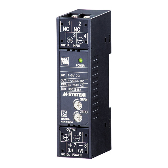
COMPONENT IDENTIFICATION
Body
Specifications
INSTALLATION
Set the unit so that its DIN rail adapter is at the bottom.
■ MOUNTING THE UNIT ON A DIN RAIL
A) Hang the upper hook at the rear side of unit on the DIN
rail.
B) Push in the lower in keeping pressing the unit to the DIN
rail.
A
■ REMOVING THE UNIT
A) Push down the DIN rail adaptor using a minus screw-
driver.
B) Pull out the lower part of the unit.
C) Remove the upper part from the DIN rail.
C
Spring Loaded
DIN Rail Adaptor
M5PT
Terminal Cover
Power LED
Span Adj.
Zero Adj.
DIN Rail
B
B
A
EM-2488 Rev.6 P. 1 / 2
Advertisement
Table of Contents

Related Manuals for M-system M5PT


Summary of Contents for M-system M5PT
- Page 1 INSTRUCTION MANUAL M5PT PT TRANSMITTER MODEL BEFORE USE ..COMPONENT IDENTIFICATION Thank you for choosing us. Before use, please check con- Body tents of the package you received as outlined below. Terminal Cover If you have any problems or questions with the product,...
- Page 2 M5PT TERMINAL CONNECTIONS ADJUSTMENT PROCEDURE Connect the unit as in the diagram below or refer to the This unit is calibrated at the factory to meet the ordered connection diagram on the front of the unit. specifications, therefore you usually do not need any cali- bration.
Need help?
Do you have a question about the M5PT and is the answer not in the manual?
Questions and answers