
Subscribe to Our Youtube Channel
Related Manuals for milleteknik PoE Switch 8p FLX M+


Summary of Contents for milleteknik PoE Switch 8p FLX M+
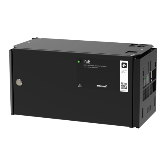
- Page 1 PoE Switch 8p FLX M+, PoE Switch 16p FLX M+ PoE switch and powersupply with battery backup...
- Page 2 350-251 Publication date 2023-11-09...
-
Page 3: Table Of Contents
1.1.3. Link to technical specifications ................5 1.1.4. Help us make better products ................5 2. About PoE from Milleteknik ......................5 3. How PoE powers devices connected to the power supply ............. 6 4. Component overview PoE FLX M ....................6 5. -
Page 4: Before You Begin
14.1. Product sheet - power supply from Milleteknik ............... 39 14.1.1. Name, article number and e-number ..............39 14.1.2. PoE ......................... 39 14.1.3. Description ....................... 39 14.1.4. Area of use ...................... 39 14.1.5. Voltage, current and power ................39 14.1.6. Backup operating time on batteries ..............40 14.1.7. -
Page 5: Support
1.1.1. Support Phone: +46 31-340 02 30 You will find answers to many questions at: www.milleteknik.se/support Telephone: +46 31- 340 02 30, e-mail: support@milleteknik.se. Support is open: Monday-Thursday 08:00-16:00, Fridays 08:00-15:00. Closed 11:30-13:15. 1.1.2. Link to the latest information Products and software are subject to updates, you will always find the latest information on our website. -
Page 6: How Poe Powers Devices Connected To The Power Supply
3. HOW POE POWERS DEVICES CONNECTED TO THE POWER SUPPLY PoE can power, for example, surveillance cameras. Connect external devices to be powered via PoE in PoE ports. Connect other devices that do not need to be power supplied in LAN ports. 4. -
Page 7: Console For Flx M And Flx L
Table 1. Component overview Symbol Explanation Brackets, reversible. Casing in powder-coated sheet metal. Power supply, (placed under the motherboard). Motherboard. Room for batteries. Eight PoE ports are clustered together and two LAN ports are clustered together. Cable entries. 5. CONSOLE FOR FLX M AND FLX L Bracket is reversible and can be mounted in two ways. -
Page 8: Batteries - Placement And Connection
Figure 3. FLX M - mount brackets Left bracket facing the front for mounting in a 19 "rack. Right bracket facing the back for wall mounting. IMPORTANT Leave 100 mm free around the air vents. 6. BATTERIES - PLACEMENT AND CONNECTION 6.1. -
Page 9: Motherboard Description
Figure 4. Wiring diagram for batteries in battery backup Connect the terminals correctly so that you do not damage the equipment. 7. MOTHERBOARD DESCRIPTION 7.1. Connect in this order To minimize the risk of errors that may occur in connection with a short circuit, connections to the motherboard must be made in this order. -
Page 10: Connect Alarm On P3
Figure 5. Description: CEO3 uP On PCB Explanation Indicator diode. Jumper for alarm control. When the jumper is mounted, the alarm limit is lowered. P1:1-3 Mains connection. P2:1-2 Load output, + / -. P2:3-4 Load output, + / -. P3:1-3 Alarm output, NC, CO, NO. -
Page 11: Connect Mains
Table 4. Load connections Circuit board number Explanation P2: 1 Connection for load 1 + P2: 2 Connection for load 1 - P2: 3 Connection for load 2 +. P2: 4 Connection for load 2 -. MAX CURRENT The maximum current must not be exceeded. Max current is indicated on nameplate on the device. -
Page 12: Control Alarm Limit
7.5. Control alarm limit Alarm for low battery voltage in battery operation can be controlled. By jumpering JU2, the limit for when the unit should give an alarm can be lowered. Alarms are given when the battery voltage in battery drops below the limit. Table 6. -
Page 13: Commissioning - How To Start The Unit
Explanation Not used. 2 pcs RJ-45 ports for data, not PoE, (powered). 8 pcs RJ-45 powered ports for connecting PoE devices. Indication, green LED lights up when device is plugged in. This is only an indication that the port is connected and not the connected device's status. - Page 14 NOTE The settings shown are settings for PC, (Windows 7 - Windows 11). Windows and names may vary between different versions of Windows. Unfortunately, we cannot provide support for settings of your computer. NOTICE The address of the PoE switch is: 192.168.2.1 and username and password are: ad- min/admin The IP address in the switch is static (fixed) and therefore the computer's IP address and subnet mask must be static.
- Page 15 Double-click Internet Protocol Version 4 (TCP / IPv4). Set the computer's IP address and subnet mask as shown in the figure below. By default, the product's IP address be 192.168.2.1. You can set any IP address as long as it is not the same as your switch's IP address and is in the same network segment as your switch's IP address.
-
Page 16: Log In To The Poe Switch
11.2. Log in to the PoE switch NOTE IP address of the switch (factory setting): 192.168.2.1 Password (factory setting): admin Start the browser on your computer. Login to PoE switch. Number Explanation IP address of the PoE switch: 192.168.2.1 Password: admin Apply = Ok Menu in the PoE switch... -
Page 17: Configuration
11.3. Configuration 11.3.1. System, configuration Letter, number Explanation PoE switch system configuration page Tick here if you are going to use DHCP, see warning below. Changes the factory default password, (admin). If you have made any changes, you need to click "Apply" to save the changes. -
Page 18: Ports, Configuration
WARNING The settings on this page normally do not need to be changed. Only change the settings if you absolutely know what you are doing. Factory reset the PoE device if it does not behave as expected after adjusting settings on this page. - Page 19 Letter, number Explanation Gates This setting normally does not need to be changed. Select the speed of the PoE switch's ports. This setting normally does not need to be changed.
-
Page 20: Vlan Configuration
11.3.3. VLAN configuration WARNING The settings on this page normally do not need to be changed. Only change the settings if you absolutely know what you are doing. Factory reset the PoE device if it does not behave as expected after adjusting settings on this page. -
Page 21: Igmp Snooping, Configuration
Load balancing between the ports. 11.3.5. IGMP Snooping, configuration WARNING The settings on this page normally do not need to be changed. Only change the settings if you absolutely know what you are doing. Factory reset the PoE device if it does not behave as expected after adjusting settings on this page. -
Page 22: Mirroring, Configuration
Switch that controls reception. 11.3.6. Mirroring, configuration WARNING The settings on this page normally do not need to be changed. Only change the settings if you absolutely know what you are doing. Factory reset the PoE device if it does not behave as expected after adjusting settings on this page. -
Page 23: Lldp Configuration
Mirroring of ports. 11.3.7. LLDP configuration WARNING The settings on this page normally do not need to be changed. Only change the settings if you absolutely know what you are doing. Factory reset the PoE device if it does not behave as expected after adjusting settings on this page. - Page 24 Letter, Explanation num- LLDP stands for "Link Layer Discovery Protocol", which is a network protocol standard used to discover and com- municate information about network devices connected to the same Ethernet network. The protocol allows devices such as switches and routers to send and receive messages containing information about the device's identification, capabilities, and connection topology.
-
Page 25: Qos, Configuration
11.3.8. QoS, configuration WARNING The settings on this page normally do not need to be changed. Only change the settings if you absolutely know what you are doing. Factory reset the PoE device if it does not behave as expected after adjusting settings on this page. -
Page 26: Poe, Configuration
Letter, num- Explanation QoS gives different network traffic different priority depending on its importance and requirements, helping to ensure that important services are delivered with sufficient bandwidth and minimal delay even when the network is under load. Sets whether QoS is active. 11.3.9. -
Page 27: Monitoring
Letter, number Explanation Power over Ehternet Turns PoE port on or off. Don't forget to press "Apply" to save changes. 11.4. Monitoring 11.4.1. Statistics, overview Letter, number Explanation Statistics, overview Traffic per port. -
Page 28: Statistics, Detailed
11.4.2. Statistics, detailed Letter, number Explanation Detailed statistics Select the port for which you want statistics. -
Page 29: Igmp Status
11.4.3. IGMP status L: Status of IGMP... -
Page 30: Lldp Statistics
11.4.4. LLDP statistics M: LLDP statistics... -
Page 31: Lldp Table
11.4.5. LLDP table N: LLDP overview. -
Page 32: Ping
11.4.6. Ping Letter, number Explanation Ping Input address to test the connection and response time. 11.5. Maintenance... -
Page 33: Reboot
11.5.1. Reboot WARNING Restart is done by PoE switch, battery backup is not restarted. Upon reboot, connected devices will lose connection. Alarm can be set to battery backup, but it disappears when the PoE switch is back on. Letter, number Explanation Rebooting the PoE switch. -
Page 34: Factory Reset
11.5.2. Factory reset WARNING Factory reset is done by PoE switch. Battery backup is not restored. On reset, connec- ted devices will lose connection. Alarm can be set to battery backup, but it disappears when the PoE switch is back on. Letter, number Explanation Factory reset the PoE switch. -
Page 35: Upload New Software
11.5.3. Upload new software WARNING Only use software you received from Milleteknik's support. Milleteknik assumes no re- sponsibility for software or consequences such as damage to the device or peripherals or other damage that may arise from uploading unapproved software. -
Page 36: Load And Save Configuration File
11.5.4. Load and save configuration file Letter, number Explanation Upload or download the switch's configuration. Select new configuration file. Upload new configuration file. Download configuration file to computer Newer Windows computers do not allow *.cfg files to be downloaded without additional approval in the browser when download- ing. -
Page 37: Log Out
11.5.5. Log out T: Log out of the switch. This does not affect the operation of the switch. 12. ALARM DISPLAYED ON CABINET DOOR In normal mode, the indicator LED shows a solid green light. -
Page 38: Maintenance
The indicator diode shows Explanation Solid green light Normal operation. Solid yellow glow Mains failure. Solid red light Battery not connected / blown fuse. When operating system: If the indicator LED is off, deep discharge protection has come into force. 13. -
Page 39: Product Sheet - Power Supply / Battery Backup
14. PRODUCT SHEET - POWER SUPPLY / BATTERY BACKUP 14.1. Product sheet - power supply from Milleteknik 14.1.1. Name, article number and e-number Name Article number E-number (SV) PoE Switch 8p FLX M FM01N10224P01008PM 51 728 97 PoE Switch 16p FLX M... -
Page 40: Backup Operating Time On Batteries
If the load varies, as with frequent opening of door locks, the time that batteries can continue to power the security system decreases. To get an estimate of reserve operating times see: www.milleteknik.se/Manualer/FaQ/Reservdrifttider/ 14.1.7. Battery and battery type PoE M-switch 8p FLX M: two 20 Ah batteries. -
Page 41: Enclosure
Tamper switch 14.1.19. Manufacturing, lifespan, environmental impact and recycling Manufactured by Milleteknik in Partille, Sweden. The product is designed and constructed for a long service life, which reduces the environmental impact. The life of the product (except wearing parts) depends on, among other things, environmental factors, mainly ambient temperature, unforeseen load on components such as lightning strikes, external impact, handling errors, etc. -
Page 42: Link To The Latest Information
at the nearest recycling station or sent back to the manufacturer. Contact your distributor for more information. 14.1.20. Link to the latest information Products and software are subject to updates, you will always find the latest information on our website. 14.1.21. -
Page 43: Address And Contact Details
16. ADDRESS AND CONTACT DETAILS Milleteknik AB Ögärdesvägen 8 B S-433 30 Partille Sweden +46 31 340 02 30 info@milleteknik.se www.milleteknik.com... - Page 44 This page is intentionally left blank.
Need help?
Do you have a question about the PoE Switch 8p FLX M+ and is the answer not in the manual?
Questions and answers