
Related Manuals for BIOPAC Systems Advanced Brain Monitoring B-ALERT X10


Summary of Contents for BIOPAC Systems Advanced Brain Monitoring B-ALERT X10
- Page 1 B-Alert X10 Hardware Manual D35-8202-2 Rev 5 20231219 Hardware Manual Distributed by BIOPAC Systems, Inc. Page 1 of 41 © 2016-2023 Advanced Brain Monitoring, Inc.
-
Page 2: Table Of Contents
B-Alert X10 Hardware Manual D35-8202-2 Rev 5 20231219 Table of Contents Table of Contents ........................2 Chapter 1. Regulatory and Safety Information ..............4 1. Indications for Use ........................... 4 2. System Description .......................... 4 3. Meaning of symbols ........................4 4. - Page 3 B-Alert X10 Hardware Manual D35-8202-2 Rev 5 20231219 Chapter 5. Post-Acquisition Procedures ................. 32 1. Removal from the Subject’s Head ....................32 2. Cleanup – UNIVERSAL (SINGLE-USE) Strips ................... 33 3. Cleanup – REUSEABLE Strips ......................34 Chapter 6. Product Information ..................36 1.
-
Page 4: Chapter 1. Regulatory And Safety Information
B-Alert X10 Hardware Manual D35-8202-2 Rev 5 20231219 Chapter 1. Regulatory and Safety Information Indications for Use The B-Alert System is not intended for the diagnosis or treatment of patients. It is intended for non-medical applications (e.g., human factors, ergonomics, neurogaming, neuromarketing, neuroleadership, team neurodynamics, brain computer interfaces, etc.) and IRB-approved human subject research. - Page 5 B-Alert X10 Hardware Manual D35-8202-2 Rev 5 20231219 The information in this manual has been carefully checked and is based on our best judgment at this time. In the interest of continued product development, Advanced Brain Monitoring reserves the right to make changes and improvements to this manual and the products it describes at any time, without notice or obligation.
- Page 6 B-Alert X10 Hardware Manual D35-8202-2 Rev 5 20231219 • This device has been tested and found to comply with the limits for commercial devices to the applicable CE/UK directives. These safety standards are designed to provide reasonable protection against harmful interference in a typical facility.
-
Page 7: Minimum Pc System Requirements
B-Alert X10 Hardware Manual D35-8202-2 Rev 5 20231219 • Discontinue use of the device in case of any significant pain. • Possible allergic reaction or skin irritation from device components (e.g., silicone and adhesive sensors, and neoprene/Velcro strap) may occur. Wearing the device may result in a mark on the subject’s forehead that usually disappears in a few hours;... -
Page 8: Chapter 2. Getting Started
B-Alert X10 Hardware Manual D35-8202-2 Rev 5 20231219 Chapter 2. Getting Started B-Alert System Components B-Alert System and Optional Accessories Components LE System Classic System Component Image B-Alert X10 Device ✓ X10 Headset (Headset) ✓ Enclosure Door with Transparent ✓ ✓... - Page 9 B-Alert X10 Hardware Manual D35-8202-2 Rev 5 20231219 Components LE System Classic System Component Image ✓ ✓ USB Charger ✓ Bluetooth Dongle (Dongle) ✓ ✓ ✓ Tape Measure ✓ 3-pin Cable (EEG) © 2016-2023 Advanced Brain Monitoring, Inc. Page 9 of 41...
- Page 10 B-Alert X10 Hardware Manual D35-8202-2 Rev 5 20231219 Components LE System Classic System Component Image ✓ 3-pin Cable (EEG) ✓ ✓ 2-pin Cable (EEG/ECG/EMG) ESU Kit (optional) Multi-channel External Synching ✓ Unit (ESU) ✓ Micro B-to-USB Charging cable ✓ Serial cable ©...
- Page 11 B-Alert X10 Hardware Manual D35-8202-2 Rev 5 20231219 Components LE System Classic System Component Image Universal (Single-Use) Sensor Strip Kits 10-20 Universal Strip* Kit • 10-20 Universal Strip (Strip) • Large Neoprene Strap ✓ ✓ (Headstrap) • Small Neoprene Strap (Doorstrap) *Medium, Small, and X-Small sizes Synapse...
-
Page 12: Required Items Not Included With The B-Alert System
B-Alert X10 Hardware Manual D35-8202-2 Rev 5 20231219 Components LE System Classic System Component Image Disposable Kit: • Foam Sensors (Donuts) • Conductive Cream ✓ • Syringe with curved tip • Tweezer • AgCl Sensors (Adhesive Electrodes) Required Items not Included with the B-Alert System •... -
Page 13: Chapter 3. Headset/Receiver
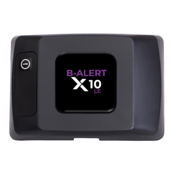
B-Alert X10 Hardware Manual D35-8202-2 Rev 5 20231219 Chapter 3. Headset/Receiver Headset Components On/Off Switch Micro-B to USB Charging Input Speaker LED Indicator 2-Pin EEG/EOG/ECG/EMG Input Sliding Locks 3-Pin EEG Input Door with Plastic Loop Adapter Input Device Feedback The Headset uses green and amber LED light indicators and may use sound to indicate operational status. These indicators do not indicate hazardous situations or alert conditions and should not be taken as alarm indicators. -
Page 14: Charging
B-Alert X10 Hardware Manual D35-8202-2 Rev 5 20231219 The Receivers use LED light indicators for common operational events. BT Receiver Event LE Dongle Classic Dongle Classic ESU Not connected to Headset Blue blinking Green & Amber on Blue blinking Connected to Headset Blue on Green on Blue on... -
Page 15: Maintaining Bt Signal Quality
B-Alert X10 Hardware Manual D35-8202-2 Rev 5 20231219 Maintaining BT Signal Quality Guidance for Technicians • Make sure the Headset and Receiver are within 30ft (10m) of each other. Transmission may work over 15m, but 10m is recommended to minimize data loss in transfer. •... -
Page 16: Sample Guidance For Subject With Placement Near A Bed
B-Alert X10 Hardware Manual D35-8202-2 Rev 5 20231219 Sample Guidance for subject with placement near a bed While the above options provide guidance for a mobile environment, see below sample of Receiver placements in relation to a subject in a bed. In the sample below yellow represents the clearance area around the participant, the green circle represents the acceptable placement of the receiving unit and laptop, and the red circle represents a bad placement of the Receiver. -
Page 17: Chapter 4. Sensor Strip
B-Alert X10 Hardware Manual D35-8202-2 Rev 5 20231219 Chapter 4. Sensor Strip For a visual demonstration of Sensor Strip preparation and application, refer to ABM’s EEG Training videos. ABM’s 10-20 Reduced Sensor Strip uses 9 of the electrodes found on the international standard 10-20 montage. Front Back Preparation... - Page 18 B-Alert X10 Hardware Manual D35-8202-2 Rev 5 20231219 3. Measure the distance (cm) from the Nasion to the 4. Measure the distance (cm) from the Ear bottom of the Inion, record the value. Pull the Attachment on one side of the head (the topmost measuring tape tautly, especially if the subject has place where the ear attaches to the head) laterally a lot of hair.
-
Page 19: Preparing 10-20 Lm Universal (Single-Use) Strips
B-Alert X10 Hardware Manual D35-8202-2 Rev 5 20231219 Extra Small Strip Medium Strip Strip Sizing Chart Small Strip Outside ABM Range Left/Right Ear Attachment Measurement (cm) 24.5 25.5 26.5 27.5 28.5 29.5 30.5 31.5 32.5 33.5 30.5 31.5 32.5 33.5 34.5 35.5 36.5... - Page 20 B-Alert X10 Hardware Manual D35-8202-2 Rev 5 20231219 5. The Strip is fully seated if the holes on the Strip 6. Once the Strip is seated, place the cover back on tail line up with the Adapter posts. the Adapter. Align the label markings on the adapter cover with the strip.
-
Page 21: Preparing 10-20 Reuseable Strips
B-Alert X10 Hardware Manual D35-8202-2 Rev 5 20231219 Preparing 10-20 REUSEABLE Strips 1. After selecting the appropriately sized Strip, 2. Place the Headstrap with the looped, or fuzzy, side inspect the entire Strip and verify there are no rips facing down and lay the Strip on the Headstrap or hard creases. -
Page 22: Preparing The Subject
B-Alert X10 Hardware Manual D35-8202-2 Rev 5 20231219 3. Refill each donut and repeat one or two more Caution: Do not overfill the donuts and cause the times until the foam is completely saturated and cream to squish outside the foam. the hole is full. -
Page 23: Application
B-Alert X10 Hardware Manual D35-8202-2 Rev 5 20231219 Application Application consists of applying the adhesive electrodes to the mastoid sites and, if ECG is used, collarbone, the prepared Sensor Strip, and the Headset. Applying the Mastoid Electrodes For the 10-20 LM, linked mastoids are used as the reference. Impedance values will typically decrease over time, so it is best to place the mastoid electrodes first. -
Page 24: Applying The Prepared Sensor Strip
B-Alert X10 Hardware Manual D35-8202-2 Rev 5 20231219 1. The adhesive electrodes do not need to be cut 2. Apply a small dab of cream on the center of the down for ECG. electrode and spread it out evenly. 3. Peel the paper backing off the electrode to expose the adhesive and apply to the right and left sides of the subject’s collarbone. - Page 25 B-Alert X10 Hardware Manual D35-8202-2 Rev 5 20231219 5. Fasten the Headstrap/Strip around the 6. Check that both sides of the Headstrap sit just circumference of the subject’s head. Fit should be above the top of the subject’s ears and the snug, but not too tight –...
- Page 26 B-Alert X10 Hardware Manual D35-8202-2 Rev 5 20231219 11. Starting at the front and moving to the back, 12. While troubleshooting, be careful to maintain the fasten the remaining Strip arms in pairs to the correct alignment of the Strip on the scalp, Headstrap using the same amount of pressure to ensure that the Strip is lying flat without any keep the center line straight.
- Page 27 B-Alert X10 Hardware Manual D35-8202-2 Rev 5 20231219 17. Working front to back, lift each Strip arm one at a 18. For best connectivity ensure sensor to scalp time. Hold the bottom of the Headstrap and peel connection. Part the hair with the curved tip of the Strip arm off the neoprene to help the Velcro the cream.
-
Page 28: Applying The Headset
B-Alert X10 Hardware Manual D35-8202-2 Rev 5 20231219 Applying the Headset 1. If the 3-pin cable and 2-pin cable (optional) are not 2. With the Headset label side down, press down in already connected to the Headset, connect them. the center of the Back Enclosure Door and slide Be sure to press the cable connector firmly into the locks away from the center of the Headset. -
Page 29: Connecting The Leads
B-Alert X10 Hardware Manual D35-8202-2 Rev 5 20231219 4. Replace the Back Enclosure Door, press down on 5. Slip the Doorstrap through the transparent plastic the center of the door and slide the locks toward loop on the door with the fuzzy, or Velcro, side the center of the Headset. -
Page 30: Troubleshooting Impedances
B-Alert X10 Hardware Manual D35-8202-2 Rev 5 20231219 Troubleshooting Impedances Turn the Headset on and establish connection with the Receiver (refer to Chapter 3 Section Refer for the B-Alert Live Software User Manual for how to obtain impedances using the acquisition software. In order to reduce impedances, additional troubleshooting may be necessary. - Page 31 B-Alert X10 Hardware Manual D35-8202-2 Rev 5 20231219 • Ill-fitted equipment could cause the strip to ride up on the subject’s head causing the foam connectors to disconnect from the scalp. • If you observe that the strip arms are too tight, or that it is difficult to get sensors to lie flat, you may need to check the strip size measurements or troubleshoot other steps of the setup.
-
Page 32: Chapter 5. Post-Acquisition Procedures
B-Alert X10 Hardware Manual D35-8202-2 Rev 5 20231219 Chapter 5. Post-Acquisition Procedures Removal from the Subject’s Head 1. When acquisition testing is complete, turn the 2. Carefully remove the EEG and ECG adhesive Headset off. sensors. Stick them to each other so that they don’t stick to the subject. -
Page 33: Cleanup - Universal (Single-Use) Strips
B-Alert X10 Hardware Manual D35-8202-2 Rev 5 20231219 Cleanup – UNIVERSAL (SINGLE-USE) Strips 1. With the Headset label side up on a flat surface, 2. Lift the strip slightly so that it clears the posts on remove the adapter board cover. the adapter board and pull the strip out of the connector. -
Page 34: Cleanup - Reuseable Strips
B-Alert X10 Hardware Manual D35-8202-2 Rev 5 20231219 7. Wipe down the Headset, strip adapter cover, and 8. Wipe the Doorstrap with an alcohol wipe and slip cables with an alcohol wipe (70% IPA). All areas it back through the transparent plastic loop with should remain wet for a minimum of 15 seconds. - Page 35 B-Alert X10 Hardware Manual D35-8202-2 Rev 5 20231219 iii. Place index finger beneath Strip Board and thumb on top of Strip Board, apply light upward pressure and lift strip straight up away from device. When the Sensor Strip is removed from the device, the Female Strip Connector on the Strip and the Male Strip Connector on the device will be visible.
-
Page 36: Chapter 6. Product Information
B-Alert X10 Hardware Manual D35-8202-2 Rev 5 20231219 Chapter 6. Product Information Technical Specifications System Specifications Brand name B-Alert Operating Modes Mode Description Monitoring Transmits via Bluetooth (BT) Hibernation Device turned off Disconnect Long term storage Signals acquired Signal Number of Default Default Interfaced to... - Page 37 B-Alert X10 Hardware Manual D35-8202-2 Rev 5 20231219 User Interface User Control ON/OFF tactile switch Acoustic audio feedback Internal speaker Visual feedback Green, Amber LED Dimensions 2.8” long x 1.9” wide x 0.8” deep Weight 0.071kg (Device with battery) Materials of Data Acquisition Device Device Enclosure Strap Neoprene with loop fastener...
-
Page 38: Fcc
B-Alert X10 Hardware Manual D35-8202-2 Rev 5 20231219 Degree of protection against electrical shock Low Voltage Directive, Electrical Equipment Regulations Mode of operation Continuous Degree of protection against ingress of water/liquids IP22 Electromagnetic compatibility Electromagnetic Compatibility Directive/Regulations EN 301 489-1, EN 301 489-17 Electrostatic Discharge EN 61000-4-2 Radio Frequency Electromagnetic Field Amplitude... - Page 39 B-Alert X10 Hardware Manual D35-8202-2 Rev 5 20231219 Guidance and manufacturer’s declaration – electromagnetic immunity The X10 System is intended for use in the electromagnetic environment specified below. The customer or the user of the X10 should assure that it is used in such an environment.
-
Page 40: Customer Support, Warranty, And Terms Of Use
B-Alert X10 Hardware Manual D35-8202-2 Rev 5 20231219 a Field strengths from fixed transmitters, such as base stations for radio (cellular/cordless) telephones and land mobile radios, amateur radio, AM and FM radio broadcast and TV broadcast cannot be predicted theoretically with accuracy. To assess the electromagnetic environment due to fixed RF transmitters, an electromagnetic site survey should be considered. -
Page 41: Additional Information
B-Alert X10 Hardware Manual D35-8202-2 Rev 5 20231219 Additional Information Trademark Acknowledgements • Windows is a trademark of Microsoft Corporation. • Synapse is a registered trademark of Med-Tek/Synapse, Arcadia, CA. All other products or brand names are trademarks or registered trademarks of their respective companies. ©...
Need help?
Do you have a question about the Advanced Brain Monitoring B-ALERT X10 and is the answer not in the manual?
Questions and answers