
Related Manuals for BIOPAC Systems NIBP250


Summary of Contents for BIOPAC Systems NIBP250
- Page 1 NIBP250 User’s Guide Noninvasive Blood Pressure Measurement System 42 Aero Camino, Goleta, CA 93117 Telephone: 805-685-0066 Facsimile: 805-685-0067 support@biopac.com www.biopac.com...
-
Page 2: Table Of Contents
3.9. Calibration ..............................13 3.9.1. Calibration Check..........................13 3.9.2. Recalibration ............................13 3.10 Triggers ............................... 13 4. Using the NIBP250 with a BIOPAC MP Acquisition System ................14 4.1. Connections ............................. 14 4.2. Software Setup in AcqKnowledge......................14 5. Technical Specifications ..........................15 6. -
Page 3: User's Manual 1. Introduction
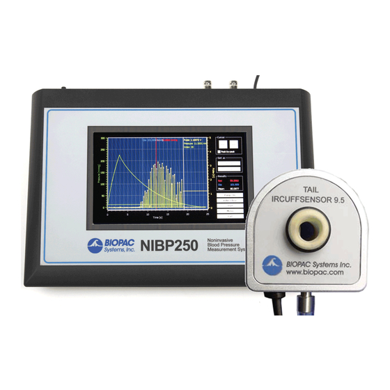
The NIBP250 noninvasive blood pressure monitor is a stand-alone device for measuring the blood pressure of small animals. The NIBP250 has a convenient touch screen LCD user interface and includes a built-in Tail Cuff Sensor pump that automatically inflates the cuff to occlude the blood vessels in the tail of a rat or similar small animal. -
Page 4: Animal Preparation
2.1. Front Panel Figure 1: Front Panel Figure 1 shows the front panel of NIBP250. It has a 7” LCD Display with a resistive-type touch screen user interface. To activate controls, touch the screen with your finger or the stylus. -
Page 5: Rear Panel
Noninvasive Blood Pressure Monitoring System 2.2. Rear Panel Figure 2: Rear Panel Table 1: Rear panel connections On/Off Switch Trigger Output Power Adaptor Input USB Memory Slot Pulse Signal Analog Output SD Card Slot Pressure Signal Analog Output Tail Sensor Input Trigger Input Tail Cuff Tubing Port 2.3. -
Page 6: Main Screen
NIBP250 User’s Guide 2.4. Main Screen The touch-sensitive Main Screen (see Figure 4) controls all operational and setup functions. All buttons on the right of the screen are also touch-sensitive. For a full explanation of onscreen buttons, see Table 2 on page 6. -
Page 7: Measurement Analysis View
Figure 5: Analysis View If the “Peak by peak” option is selected, the NIBP250 automatically detects the peaks of the pulse signal and marks them with white crosses as seen in Figure 5. Touching anywhere on the plotting will bring up a cursor. -
Page 8: Menu Window
NIBP250 User’s Guide 2.5. Menu Window The NIBP250 Menu window (see Figure 6) can be displayed by pressing the “Menu” button on the Main Screen while no measurement process is running. The General, Options and Calibration tabs are used for accessing and adjusting the NIBP250 global settings. -
Page 9: Options
Noninvasive Blood Pressure Monitoring System After setting the Date/Time Properties, click “OK” at the top right of the window to accept the new settings. To discard settings without saving changes, click the “X” button. The “Pulse gain” and the “Cut Off Pressure” are adjusted by moving the sliders left or right. Click OK to accept any modified settings. -
Page 10: Usage
In a standard cuff using the "auscultatory" method, the diastolic pressure is determined by the last pulse detected as the signal falls back to baseline. In the NIBP250, which uses the "oscillometric" method, the diastolic pressure is aligned with the peak pulse detected. -
Page 11: Working With Saved Results
Figure 12: Location of Systolic and Diastolic Pressures The NIBP250’s automated peak detection system marks the peak of each pulse with a white cross, and is enabled by selecting the "Peak by peak" option on the Main Screen. This feature makes it easier to identify the individual pulses. -
Page 12: Result File
3.6. Result File After measurements are performed, the pressure and pulse signals (including the analysis results) can be saved to NIBP internal memory, SD Card or USB Memory. If you insert any external memory NIBP250 uses it instead of its internal storage. -
Page 13: Calibration
To start a measurement using the trigger, Enable the “Trigger Input option” checkbox in the Options Tab (see 2.5.2. Options) and then press the “Start” button. NIBP250 will wait until the trigger is initiated before acquiring the measurement . To trigger the measurement the trigger input signal must be set low. -
Page 14: Using The Nibp250 With A Biopac Mp Acquisition System
From the new module list, select UIM100C-A2 (or whichever channel CBL150-PLS pulse cable is connected to) and click “Add.” b. From the UIM100C Transducer list, select “NIBP250 – Small Animal Tail BP, Pulse” and click OK. Page 14 of 18... -
Page 15: Technical Specifications
Noninvasive Blood Pressure Monitoring System 5. Technical Specifications Table 4: Technical Specifications Specification Value Cut-off Pressure Range 100 – 300 mmHg (adjustable by 50mmHg steps) Pressure Accuracy 300 mmHg Full Scale 1% Pressure Sensitivity 0.1 mmHg Pressure Signal Output 300 mmHg / 3 Volt DC Pulse Gain Levels x1, x2, x4, x5, x8, x16, x32 (adjustable) Pulse Signal Output... -
Page 16: Troubleshooting
6.2. Compressor runs continuously Immediately Turn off the NIBP250 system. Remove the Tubing from the Cuff connector on the rear panel of NIBP250 Turn the system back on. Close the air outlet by pressing the finger on the Cuff output and press the “Start” button. The compressor will work for a few seconds and stop (please inform BIOPAC if the Compressor does not stop). -
Page 17: Accessories
Noninvasive Blood Pressure Monitoring System 7. Accessories Table 5 lists the available accessories for the NIBP250 system. Table 5: Accessories Item Description RXTCUFSENSOR9.5 Tail Cuff Sensor 9.5 mm RXTCUFSENSOR11 Tail Cuff Sensor 11 mm RXTCUFSENSOR13 Tail Cuff Sensor 13 mm RXCUFSEN9.5-MRI... -
Page 18: Maintenance And Care
8. Maintenance and Care 8.1. Service Policy The display unit of the NIBP250 does not require any routine maintenance. Should service be required, it should be performed by a qualified technician. All maintenance and repair procedures should be directed to BIOPAC.
Need help?
Do you have a question about the NIBP250 and is the answer not in the manual?
Questions and answers