Table of Contents
Advertisement
Quick Links
Advertisement
Table of Contents

Subscribe to Our Youtube Channel
Related Manuals for Chauvet Professional REM1


Summary of Contents for Chauvet Professional REM1
- Page 1 User Manual Model ID: REM1 Model ID: REM1SQ...
- Page 2 Edition Notes The REM 1 and REM 1SQ User Manual includes a description, safety precautions, installation, programming, operation and maintenance instructions for the REM 1 and REM 1SQ as of the release date of this edition. Trademarks Chauvet, the Chauvet logo, and REM are registered trademarks or trademarks of Chauvet & Sons, LLC (d/ b/a Chauvet and Chauvet Lighting) in the United States and other countries.
-
Page 3: Table Of Contents
Table of Contents TABLE OF CONTENTS 1. Before You Begin ............... What Is Included.................. Claims....................Text Conventions................. Symbols....................Safety Notes ..................FCC Statement of Compliance ..............Expected LED Lifespan ............... 2. Introduction ................Product Description ................Features....................Required Accessories................Optional Accessories ................Available Power Cables................ - Page 4 Table of Contents Horizontal Panel Connection ..............6. Connecting & Cabling Each REM 1 and REM 1SQ....Testing Signal and Power Connections..........Using the REM 1 and REM 1SQ Test Button........Connecting Power and Signal Cables ..........Connecting the Signal Between Joined Panels ........Signal Chain Rectangles .................
-
Page 5: Before You Begin
Before You Begin 1. Before You Begin What Is Included REM1 • 1 case (4 REM1) • 4 Seetronic® etherKON® signal linking cables • 1 Seetronic® PowerKON® power cable • 5 spare LED masks • 4 Seetronic® PowerKON® power linking cables •... -
Page 6: Safety Notes
Before You Begin Safety Notes Read all the following safety notes before working with this product. These notes contain important information about the installation, usage, and maintenance of this product. This product contains no user-serviceable parts. Any reference to servicing in this User Manual will only apply to properly trained, certified technicians. -
Page 7: Fcc Statement Of Compliance
Before You Begin FCC Statement of Compliance This device complies with Part 15 Part B of the FCC rules. Operation is subject to the following two conditions: 1. This device may not cause harmful interference, and 2. This device must accept any interference received, including interference that may cause undesired operation. -
Page 8: Introduction
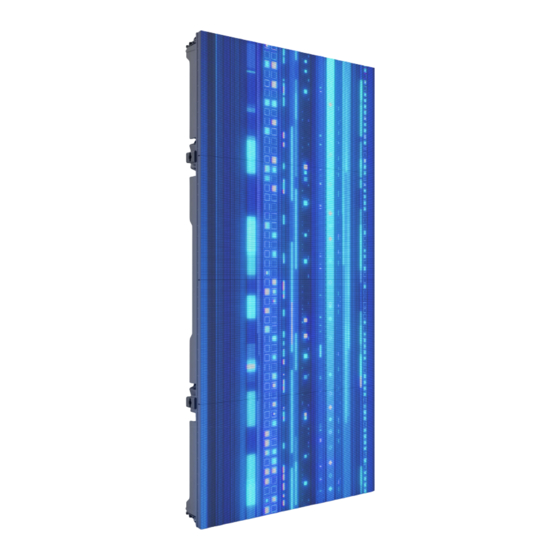
Introduction 2. Introduction Product Description REM 1 is a high-resolution 800 NITS indoor video wall solution with a 1.9mm pitch, integrated convex/ concave curving capabilities, and universal magnetic LED modules. Its DCI-P3 color gamut LEDs offer 26% more color possibilities compared to standard sRGB/Rec.709 LEDs. With high-speed 7680Hz LED drivers, A10s Pro Novastar Receiving cards, and low latency, REM 1 offers top-tier performance and signal processing for VR/XR applications, exhibits, houses of worship, installations and indoor events. -
Page 9: Product Overview
Introduction Product Overview Receiver Alignment conical (x2) M10 threaded M10 threaded mounting hole mounting hole Latch Curve receiver Test button power/ signal indicator LEDs Seetronic powerkon in Seetronic powekon out Curve receiver Latch Seetronic etherkon Seetronic etherkon signal through port signal through port Latch Latch... -
Page 10: Pixels Per Panel
Introduction Pixels per Panel LED module REM 1 REM 1SQ Each pixel is 1 tri-color LED. The following table provides the pixels per panel in each REM 1 and REM 1SQ. For detailed specifications, refer to the Technical Specifications table at the end of this User Manual. -
Page 11: Rem 1 And Rem 1Sq Led Module Insertion And Removal
Introduction REM 1 and REM 1SQ LED Module Insertion and Removal Removing a Module from the Rear To remove an LED module from the rear of the REM 1 and REM 1SQ: 1. Identify which module needs to be removed. 2. -
Page 12: Inserting A Module
Introduction Inserting a Module In order to insert a module onto the panel, simply reverse the steps outlined in Removing a Module from the Rear. If the module is placed on the right side of the panel, place the connector cover on the right side connector. -
Page 13: Removing And Replacing The Led Masks
Introduction Removing and Replacing the LED Masks 8 masks per REM 1 and REM 1SQ module To replace one of the LED masks on an REM 1 and REM 1SQ LED module, follow the instructions below: 1. Remove the module from the REM 1 and REM 1SQ (see REM 1 and REM 1SQ LED Module Insertion and Removal). -
Page 14: Product Dimensions
Introduction Product Dimensions 0.4 in 10 mm 0.5 in 12 mm 1.4 in 36 mm 9.84 in 250 mm 39.36 in 1000 mm 4.52 in 115 mm 19.7 in 500 mm 2.74 in 70mm 4.7 in 120 mm REM 1 and REM 1SQ User Manual Rev. 1... -
Page 15: Setup
Additional Products Product Source All REM 1 and REM 1SQ panels support power linking. Refer to the following table for specifications. Voltage REM1 REM 1SQ @ 120 V, 60 Hz @ 208 V, 60 Hz @ 230 V, 50 Hz Please refer to all applicable local codes and regulations for the proper installation of this product. -
Page 16: Mounting
Mounting 4. Mounting Orientation Each REM 1 and REM 1SQ is constructed of aluminum. This ensures each panel is stable and easy to install. Each panel also has convenient built-in handles located on the top and bottom of the backside of the panel along with two alignment conicals on the top and two alignment bolts (feet) on the bottom. -
Page 17: Rem-Rb 50Cmip Curve Dual Function Rig Bar Dimensions
Mounting REM-RB 50CMIP CURVE Dual Function Rig Bar Dimensions Sold Separately 19.67 in 499.6 mm 4.72 in 120 mm 2.36 in 60 mm REM-RB 100CMIP Dual Function Rig Bar Dimensions Sold Separately 39.35 in 999.6 mm 4.72 in 120 mm 2.36 in 60 mm REM 1 and REM 1SQ User Manual Rev. -
Page 18: Mounting/Hanging With Dual Function Rig Bar
Mounting Mounting/hanging with Dual Function Rig Bar Bottom View Rig bar latch Spring knob Alignment Side View Tightening Locking bar holes (x2) Alignment magnets (x3) knob Alignment conical (x2) Back View Curve Alignment bolts receiver Latch connection connection (For use with DRB Curve Kit) Alignment conical (x2) -
Page 19: Curving The Panels
Mounting Curving the Panels The curve receiver of the REM 1 and REM 1SQ and REM -RB50 CM IP Curve allows a convex or concave angle between rig bars and video panels without additional accessories. To set the angle to -5° (convex), -2.5° (convex), 0° (straight), +5° (concave), or +10° (concave): 1. -
Page 20: Truss Installation
Mounting Truss Installation Attach to Truss Using Dual Function Rig Bar The M10 mounting points are not intended for hanging or suspending from a truss or other overhead structure. In order to suspend/hang the panels from a truss or other overhead structure, use the Dual series rig bars (REM-RB50CMIPCURVE or REM-RB100CMIP, sold separately). -
Page 21: Mounting/Stacking With Dual Function Rig Bar
Mounting Mounting/Stacking with Dual Function Rig Bar Alignment holes (x4) Top View Receiver connection Back View Latch connection Alignment conical (x2) Alignment hole Receiver connection (For use with DRB Curve Kit or Ground Support 2 Kit) TR16 Screw Jacks (10 included with Ground Support 2 Kit) 1. -
Page 22: Flat Wall Installation
Mounting Flat Wall Installation Refer to the following diagrams for flat wall installation. Mounting Points on a Flat Wall Rear Front Threaded Mounting Holes Mounting Holes Size M10 (x4) Size M8 (x4) At least 1 mounting point for every junction (circled) must M10 bolts must be M8 bolts are be secured, including outside... -
Page 23: Flat Wall Installation
Mounting Flat Wall Installation When mounting to a flat wall, use 6.5 mm thick spacers at each mounting point, between the panels and the struts, as in the diagram below. Strut nut washer Steel Strut LED Module Washer (x2) (spacer) Washer M8 Bolt Strut nut... -
Page 24: Safety Cable Installation
Mounting Safety Cable Installation Safety cables may be attached to the REM 1 and REM 1SQ. To attach safety cables to the REM 1 and REM 1SQ, follow the instructions below: 1. Attach the clip at one end of the safety cable to the handle of the module. 2. -
Page 25: Joining Each Rem 1 And Rem 1Sq
Joining Each REM 1 and REM 1SQ 5. Joining Each REM 1 and REM 1SQ Vertically Joining the Panels Each REM 1 and REM 1SQ can be easily joined vertically to a truss using an optional rig bar and the 2 receiver connections located at the top of each panel. -
Page 26: Vertical Panel Connection
Joining Each REM 1 and REM 1SQ Vertical Panel Connection Use the following instructions to join panels vertically: 1. Line up the alignment conicals at the top of each panel, and the alignment magnets at the top and bottom of each panel. 2. -
Page 27: Horizontally Joining The Panels
Joining Each REM 1 and REM 1SQ Horizontally Joining the Panels Each REM 1 and REM 1SQ can be joined horizontally using the latch connections on the inside, upper and lower left sides of each panel. Horizontal Panel Connection Use the following instructions to join panels horizontally: 1. -
Page 28: Connecting & Cabling Each Rem 1 And Rem 1Sq
Connecting & Cabling Each REM 1 and REM 1SQ 6. Connecting & Cabling Each REM 1 and REM 1SQ Testing Signal and Power Connections Each REM 1 and REM 1SQ have 2 power sockets and 2 signal ports. The following table outlines each of the indicator functions. -
Page 29: Connecting Power And Signal Cables
Connecting & Cabling Each REM 1 and REM 1SQ Connecting Power and Signal Cables The following sections provide information and diagrams on connecting signal and power between panels. Refer to the Introduction Operation sections in this User Manual for available cables and item numbers. Connecting the Signal Between Joined Panels Signal cable panel connections can use several different configurations. -
Page 30: Signal Chain Rectangles
Connecting & Cabling Each REM 1 and REM 1SQ Signal Chain Rectangles When panels are assembled together to output video from a Novastar MX40 Pro, they form horizontal rows and vertical columns in rectangular arrangements. Each port of one of the Novastar MX40 Pro driver can support multiple REM 1 and REM 1SQ panels. If the amount of panels used exceeds the maximum, more than 1 output port from the Novastar MX40 Pro will be required. -
Page 31: Connecting The Power Between Joined Panels
Connecting & Cabling Each REM 1 and REM 1SQ Connecting the Power Between Joined Panels Power cable panel connections can also use different configurations. The basic configuration to connect the main power supply from one panel to the next is: 1. -
Page 32: Led Module Care And Replacement
LED Module Care and Replacement 7. LED Module Care and Replacement REM 1 and REM 1SQ Modules Each REM 1 and REM 1SQ has 4 or 8 LED modules connected to the panel frame by magnets. Each module has connectors that connect to the main processing unit. Module Description To ensure consistent color matching and output, replace damaged or defective modules with the same LED lot # as the others on the panel. -
Page 33: Rem 1 And Rem 1Sq Serviceability
REM 1 and REM 1SQ Serviceability 8. REM 1 and REM 1SQ Serviceability Control module The REM 1 and REM 1SQ control module can be accessed and serviced from either the front of the panel or the rear of the panel at any time, so panels can be serviced when access to either the front or the rear is restricted or impossible. -
Page 34: Typical Rem 1 And Rem 1Sq Hanging Installation
Typical REM 1 and REM 1SQ Hanging installation 9. Typical REM 1 and REM 1SQ Hanging installation Because a video wall system can include different components to provide a simple to complex modular wall design, use the following steps as a general guide to get started. Step 1 Open and examine the REM 1 and REM 1SQ road case to make sure all products and accessories are present and that each one is in good condition. -
Page 35: Operation
Operation 10. Operation Additional Hardware and Software In addition to the panels, the user will need other hardware and software to design, build, and operate the REM 1 and REM 1SQ video wall system. The following table summarizes these additional items—some are required and others are optional. -
Page 36: Operating Nova Vmp
Operation Operating Nova VMP Selecting a Processor After launching the software, Nova VMP will detect all connected processors and auto-populate the device list. To select a processor. 1. Launch Nova VMP software and locate the Device list menu. 2. Under the Device list menu, select the desired processor (i.e. Novastar MX40 Pro). 3. -
Page 37: Selecting A Signal Source
Operation Selecting a Signal Source To select a source: 1. Ensure that the Source tab is selected. Locate the source list at the bottom of the screen. 2. Select the desired signal. REM 1 and REM 1SQ User Manual Rev. 1... -
Page 38: Customizing The Canvas
Operation Customizing the Canvas The canvas is located at the center of the screen. Users can toggle between three different options to customize the canvas. To customize the canvas: 1. Locate the three custom mapping buttons above the canvas. 2. Each button will customize the canvas differently. Select the Cabinet only button and all panels will be visible on the canvas. - Page 39 Operation 3. Select the Source Only button and the source will be visible on the canvas. 4. Select Both to show the source and cabinet option on the canvas. REM 1 and REM 1SQ User Manual Rev. 1...
-
Page 40: Mapping Video Panels
Operation Mapping Video Panels In order to apply various features on the NOVA VMP software, the video panels must first be mapped. To map video panels using the Nova VMP software: 1. Ensure that the Layout tab is selected. Locate the Ports window at the bottom of the display. 2. - Page 41 Operation 4. Press and hold to select the desired panel on the canvas. Drag the panel to map it on the canvas. Follow the previous steps to map the entire canvas. REM 1 and REM 1SQ User Manual Rev. 1...
-
Page 42: Changing The Video Panel Orientation
Operation Changing the Video Panel Orientation It is possible to move the REM 1 and REM 1SQ panels without manually dragging them within the canvas. To change the video panel orientation: 1. Ensure the Layout tab is selected. Select the panel on the canvas to be moved. 2. -
Page 43: Rotating The Video Panel Orientation
Operation Rotating the Video Panel Orientation When mounting REM 1 and REM 1SQ panels sideways (90° or 270°), their orientation must be set in the mapping software. To do this through Nova VMP: 1. Ensure the Layout tab is selected. Select the panel on the canvas to be moved. 2. -
Page 44: Updating Cabinet Firmware
Operation Updating Cabinet Firmware To update the firmware of REM 1 and REM 1SQ products through VMP. 1. Select the Tools menu from the menu bar. 2. Select maintain from the tools menu. 3. Under the new display, select the cabinet tab to provide access to the firmware installation. 4. -
Page 45: Updating Controller Firmware
Operation Updating Controller Firmware To update the controller: 1. Follow steps 1-2 from the previous section. 2. Under the new display, select the controller tab to provide access to the firmware installation. 3. Select the desired update location by selecting the corresponding box(es). REM 1 and REM 1SQ User Manual Rev. -
Page 46: Technical Information
Technical Information 11. Technical Information REM 1 and REM 1SQ Maintenance To maintain optimum performance and minimize wear, the user should clean this product regularly. Usage and environment are contributing factors in determining the cleaning frequency. As a rule, clean this product at least twice a month. Dust build-up reduces light output performance and can cause overheating. -
Page 47: Technical Specifications
Technical Specifications 12. Technical Specifications REM1 Light Source Red Wavelength Green Wavelength Blue Wavelength Tri-color RGB SMD 1212 LED 620 to 625 nm 510 to 535 nm 485 to 475 nm Pixels per Panel Pixel Pitch Pixel Density Display Refresh Rate... - Page 48 Technical Specifications REM1SQ Light Source Red Wavelength Green Wavelength Blue Wavelength Tri-color RGB SMD 1212 LED 620 to 625 nm 510 to 535 nm 485 to 475 nm Pixels per Panel Pixel Pitch Pixel Density Display Refresh Rate (between LEDs) 256 x 256 (131,072 total) 1.9 mm 262,144/m...
-
Page 49: Contact Us
Contact Us Contact Us General Information Technical Support Chauvet World Headquarters Address: 3360 Davie Rd. Voice: (844) 393-7575 Davie, FL 33314 Fax: (954) 756-8015 Voice: (954) 577-4455 Email: chauvetcs@chauvetlighting.com Fax: (954) 929-5560 Toll Free: (800) 762-1084 Website: www.chauvetprofessional.com Chauvet Europe Ltd Address: Pod 1 EVO Park Email: UKtech@chauvetlighting.eu...
Need help?
Do you have a question about the REM1 and is the answer not in the manual?
Questions and answers