Table of Contents
Advertisement
Quick Links
Advertisement
Table of Contents

Related Manuals for Chauvet Professional F4XIP


Summary of Contents for Chauvet Professional F4XIP
- Page 1 User Manual...
- Page 2 F4XIP as of the release date of this edition. Trademarks CHAUVET, the Chauvet logo, and F4XIP are registered trademarks or trademarks of Chauvet & Sons, LLC (d/b/a Chauvet and Chauvet Lighting) in the United States and other countries. Other company and product names and logos referred to herein may be trademarks of their respective companies.
-
Page 3: Table Of Contents
Flat Wall Installation ................Mounting Points on a Flat Wall ..............Mounting with Steel Struts ............... Spacers (Flat Wall Installation) ..................5. Joining Each F4XIP (Creating a Modular Design)....Vertically Joining the Panels..............Vertical Panel Connection ............... Horizontally Joining the Panels ............ - Page 4 Table of Contents 6. Connecting (Cabling) Each F4XIP ..........Testing Signal and Power Connections..........Using the F4XIP Test Button ............... Connecting Power and Signal Cables ..........Connecting the Signal Between Joined Panels ........Custom Resolutions................. Signal Chain Rectangles (F4XIP) ............
-
Page 5: Before You Begin
Important installation or configuration information. The product may not function correctly if this information is not used. Useful information. F4XIP User Manual Rev. 1... -
Page 6: Safety Notes
LEDs, contributing to shorter lifespans if always used at full intensity. The average LED lifespan is 40,000 to 50,000 hours. To extend LED lifespan, maintain proper ventilation around the product, and limit the overall intensity. F4XIP User Manual Rev. 1... -
Page 7: Introduction
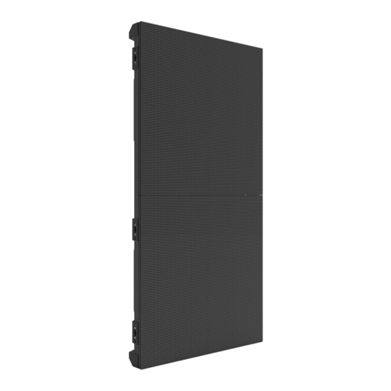
2. Introduction Product Description The F4XIP is a high performance IP65 outdoor-rated video panel with brilliant SMD 1921 LEDs outputting 5,000 NITS with a dynamic contrast ratio of 3,300:1. Video and images stand out both indoors and outdoors – even in broad daylight. Specialized LED drivers with S-PWM and an impressive display refresh rate of 3,840 Hz enhance on-camera performance. -
Page 8: Product Overview
® ® Seetronic Seetronic Alignment ® ® Powerkon Powerkon Conicals (IP65 covers (IP65 covers not shown) not shown) Alignment ® ® Alignment Seetronic Etherkon Bolts (x4) Magnets Signal Through Ports (x4) (IP65 covers not shown) F4XIP User Manual Rev. 1... -
Page 9: Pixels Per Panel
Introduction Pixels per Panel LED Module Each pixel is 1 tri-color LED. The following table provides the pixels per panel in each F4XIP. For detailed specifications, refer to the Technical Specifications table at the end of this User Manual. Parameter... -
Page 10: Product Dimensions
19.68 in 500 mm 18.66 in 474 mm 17.48 in 444 mm 39.37 in 37.17 in 1000 mm 944 mm 14.21 in 361 mm 4 mm 5 mm 3.25 in 2.46 in 82.5 mm 62.55 mm F4XIP User Manual Rev. 1... -
Page 11: Setup
3. Setup AC Power The F4XIP has an auto-ranging power supply and it can work with an input voltage range of 100 to 240 VAC, 50/60 Hz. To determine the product’s power requirements (circuit breaker, power outlet, and wiring), use the current value listed on the label affixed to the product’s back panel, or refer to the product’s specifications chart. -
Page 12: Mounting
The F4XIP can be assembled to provide any number of modular designs. The panels on the top can be securely hung from a truss or other stable surface. Always hang in a safe position with adequate space for ventilation, configuration, and maintenance. -
Page 13: Drb-F50Cm Dual Function Rig Bar Dimensions
2.36 in 60 mm DRB-F100CM Dual Function Rig Bar Dimensions Sold Separately 6.65 in 4.72 in 169 mm 120 mm 5.2 in 39.35 in 132 mm 999.6 mm 39.55 in 1,007.4 mm 2.36 in 60 mm F4XIP User Manual Rev. 1... -
Page 14: Mounting With Dual Function Rig Bar (Hanging)
Connection) only after ensuring the alignment is correct. To detach the Rig Bar from the F4XIP, reverse the previous steps. Tilt the panels away from each other to safely release the magnetic attachments. The alignment magnets on the F4XIP and Dual Function Rig Bar are designed to temporarily hold the weight of the panel to allow the user to properly align and tighten the panel into place. -
Page 15: Truss Installation
All Rig Bars in a panel assembly must be mounted individually to the mounting point! Adjacent Rig Bars will NOT support the attached weight! WARNING: This product should only be used by competent and qualified persons. F4XIP User Manual Rev. 1... -
Page 16: Mounting With Dual Function Rig Bar (Stacking)
Do not release panel until the hanging hardware has been fully secured. Removing the Feet To remove the feet (alignment bolts) from the F4XIP, twist them counter-clockwise with a 5 mm wrench until they come loose. 5 mm... -
Page 17: Flat Wall Installation
Spacers greater than 5 mm thick must be used at each mounting point, between the panels and the struts. The illustrations above are examples only. Please refer to all applicable local codes and regulations for the proper installation of the product. F4XIP User Manual Rev. 1... -
Page 18: Spacers (Flat Wall Installation)
When mounting to a flat wall, spacers greater than 5 mm thick must be used at each mounting point, between the panels and the struts, as in the diagram below. Spacer Module (>5 mm) M10 Bolt Steel Strut F4XIP User Manual Rev. 1... -
Page 19: Joining Each F4Xip (Creating A Modular Design)
Vertically Joining the Panels Each F4XIP can be easily joined vertically to a truss using an optional rig bar and the 2 female Speego connections located at the top corners of each panel. Use the male Speego connections at the bottom of each panel to connect additional panels. -
Page 20: Vertical Panel Connection
Joining Each F4XIP (Creating a Modular Design) Vertical Panel Connection Use the following instructions to join panels vertically: Line up the alignment conicals at the top of each panel, and the alignment magnets at the top and bottom of each panel. -
Page 21: Horizontally Joining The Panels
Joining Each F4XIP (Creating a Modular Design) Horizontally Joining the Panels Each F4XIP can be easily joined horizontally using the Speego connections on the inside, upper and lower left sides of each panel. Horizontal Panel Connection Use the following instructions to join panels horizontally: Align each of the panels’... -
Page 22: Connecting (Cabling) Each F4Xip
Using the F4XIP Test Button Each F4XIP has a Test button, used to ensure all LEDs are functional. Use the Test button on each panel to perform a self-test. If self-testing, you must perform the test individually for each F4XIP. You do not need to connect to a signal or use software. -
Page 23: Connecting Power And Signal Cables
Using this panel configuration with this input resolution may cause distortion. To compensate for this restraint, lower the refresh rate. Doing this can make it possible for a height of up to 10 F4XIP panels at 30 Hz, depending on the resolution width and height. -
Page 24: Signal Chain Rectangles (F4Xip)
Nova, they form horizontal rows and vertical columns in rectangular arrangements. Each port of one of the above mentioned VIP Drive products can connect to 30 F4XIP panels. If more than 30 panels are used, more than 1 output port from the VIP Drive will be required. -
Page 25: Connecting The Power Between Joined Panels
The connections continue until all panels are connected. Connect power between the panels using the same procedure as the signal only using the Power Input and Power Output connectors. You must adhere to the power-linking specifications for each F4XIP model. Refer to the... -
Page 26: Led Module Care And Replacement
A and B Modules The F4XIP has 2 types of modules, designed to only plug in to the Service Module from one direction. Check the orientation of the LED LOT # label to determine whether the module is an A type (top half, connector down) or a B type (bottom half, connector up). -
Page 27: F4Xip Led Module Removal
F4XIP LED Module Removal LED Module Thumbscrews Before an LED module can be removed from the F4XIP, 2 thumbscrews must be loosened. Identify the module that needs to be removed. Loosen the 2 thumb screws securing the module to the frame. -
Page 28: Removing A Module From The Front
LED Module Care and Replacement Removing a Module from the Front To remove an LED module from the front of an F4XIP or F4XIPSQ, use the included front service tool. Follow the instructions under LED Module Thumbscrews. Arrange the front service tool on the module to be removed so that each thumbscrew on the front service tool aligns with a threaded hole on the front of the module. - Page 29 Set the old module on a flat, stable surface, and remove the front service tool by loosening the thumbscrews until it comes free. Reverse the steps to install the replacement module. WARNING! The magnets on the modules are very powerful! Keep fingers clear when installing. F4XIP User Manual Rev. 1...
-
Page 30: Removing A Module From The Rear
LED Module Care and Replacement Removing a Module from the Rear To remove an LED module from the rear of the F4XIP: Identify which module needs to be removed. Carefully grip the module by the handles from the rear of the panel assembly. -
Page 31: Removing And Replacing The Led Masks
Orientation arrows 8 Masks per Module Rear Side To replace one of the LED masks on an F4XIP LED module, follow the instructions below: Remove the module from the F4XIP (see F4XIP LED Module Removal). Remove the 20 screws securing the mask with a Phillips-head screwdriver. -
Page 32: F4Xip Serviceability
Module The F4XIP service module can be accessed and serviced from either the front of the panel or the rear of the panel at any time, so panels can be serviced when access to either the front or the rear is restricted or impossible. - Page 33 All components in the service module are attached to the cover. To access the F4XIP service module from the rear of the panel, remove the 4 screws indicated in the diagram below. Use caution when removing these screws, as the cover of the service module will be detached from the panel frame.
-
Page 34: Typical F4Xip Installation (Hanging)
Open and examine the F4XIP road case to make sure all products and accessories have been received and that each one is in good condition. Step 2 Apply power and run the self-test for each F4XIP to ensure all LEDs and inside connections in each panel are working (optional). Step 3 Create a stable mounting surface (e.g., truss or other stable surface) for F4XIP mounting. -
Page 35: Operation
Total panel orientation (when compatible) The RCFGX file does not contain brightness/chroma calibration data or mapping data (panel layout). Each of these are stored as separate files.To load a new RCFGX file onto an F4XIP panel, follow the steps under Updating RCFGX Files (NovaLCT) Updating RCFGX Files (SmartLCT). -
Page 36: Updating Rcfgx Files (Novalct)
Operation Updating RCFGX Files (NovaLCT) To update the RCFGX files of F4XIP products through NovaLCT: 1. Connect the VIP Drive being used to a computer with NovaLCT installed. 2. Open the NovaLCT software. 3. Click User (U) in the menu running across the top of the window to open the drop-down menu. -
Page 37: Rotating The Video Panel Orientation (Novalct)
12. When the file is loaded successfully, press OK to close the confirmation window. Rotating the Video Panel Orientation (NovaLCT) When mounting F4XIP panels sideways (90° or 270°), their orientation must be set in the mapping software. To do this through NovaLCT 1. -
Page 38: Updating Rcfgx Files (Smartlct)
3. Open a saved design or create a new design and map the products as needed. 4. Select the desired products (of the same type) from the products which are mapped. 5. Right click on one of the selected products (F6 Strip IP from Chauvet Professional shown for example purposes only). -
Page 39: Technical Information
As a rule, clean this product at least twice a month. Dust build-up reduces light output performance and can cause overheating. This can lead to reduced light source life and increased mechanical wear. To clean an F4XIP, follow the recommendations below: 1. Unplug the panel from power. -
Page 40: Technical Specifications
5 @ 30 Hz 7 @ 30 Hz 10 @ 30 Hz Ordering Product Name Item Name Item Code UPC Number F4XIP (4-Pack Road Case) F4XIPX4 23091665 781462220136 UL 60950-1 CSA C22.2 No. 60950-1 E113093-1110, E113093-1125 F4XIP User Manual Rev. 1... -
Page 41: Contact Us
Lerma, Edo. de México, CP 52000 Voice: +52 (728) 690-2010 Visit the applicable website above to verify our contact information and instructions to request support. Outside the U.S., U.K., Ireland, Benelux, France, Germany, or Mexico, contact the dealer of record. F4XIP User Manual Rev. 1...
Need help?
Do you have a question about the F4XIP and is the answer not in the manual?
Questions and answers