
Subscribe to Our Youtube Channel
Related Manuals for Ozone Solutions DR-10


Summary of Contents for Ozone Solutions DR-10
- Page 1 DR SERIES HIGH OUTPUT SHOCK TREATMENT OZONE GENERATOR MODEL: DR-10 INSTALLATION & OPERATIONS MANUAL 451 Black Forest Road Hull, Iowa 51239 USA P 712.439.6880 F 712.439.6733...
-
Page 3: Table Of Contents
INSTALLATION & OPERATIONS MANUAL CONTENTS APPENDIX A - CAD DRAWING ........ 9 Introduction ..............4 I. SAFETY APPENDIX B - MAINTENANCE ......10 Precautions..............4 APPENDIX C - SAFETY DATA SHEET ....11 Personal Safety ..............5 II. COMPONENTS Diagram ................6 Description ..............6 III. INSTALLATION & OPERATION Requirements ..............6 Operator Instructions .............7 IV. -
Page 4: Introduction
INTRODUCTION THEORY OF OPERATION Ozone naturally attaches to most organic chemical The DR-10 is an ozone generation system that uses contaminants, mold spore, odors, etc. It is able to ambient air to produce concentrated ozone gas. This break them down on the moleccular level leaving the system generates ozone via corona discharge. -
Page 5: Personal Safety
INSTALLATION & OPERATIONS MANUAL PERSONAL SAFETY In most circumstances, a very small amount of ozone will be contained within the system after shutdown; Flushing ozone from the system therefore, exposure will be minimal. Safety warnings regarding ozone gas are found at the If the machine cannot be operated prior to maintenance beginning of this manual. -
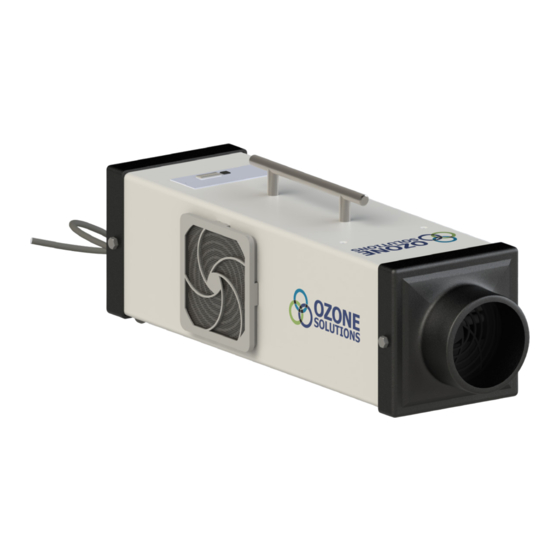
Page 6: Components Diagram
OZONE SOLUTIONS II. COMPONENTS DIAGRAM DESCRIPTION 1. Timer: The timer acts as the on/off switch for the 2. Power Cord system. It can be set to various timing options as 3. Inlet Filter well as a “hold” setting. 4. Ozone Out Port III. -
Page 7: Operator Instructions
INSTALLATION & OPERATIONS MANUAL Electrical 3. Pressing the black button on the timer will start the system and begin ozone production. The timer This requires an electrical input of 120 Volts A/C, will start at the “hold” setting, which results in single phase. -
Page 8: Warranty
Ozone Solutions will honor without notice. Because of this, Ozone Solutions is not the manufacturer’s warranty, but if and when advised obligated to replace warranty defective part(s) and/or by the manufacturer, may have the customer deal product with the same original part or product. -
Page 9: Appendix A - Cad Drawing
APPENDIX A - CAD DRAWING DR SERIES... -
Page 10: Appendix B - Maintenance
3 months or as needed Foam Filter Replacement The DR-10 is designed to operate continuously with little to no maintenance. If the unit does not produce its maximum ozone output, the following cleaning process can be performed: • Unplug the DR-10 from its power source and re-move end cap. -
Page 11: Appendix C - Safety Data Sheet
APPENDIX C - SAFETY DATA SHEET DR SERIES... - Page 12 Hull, Iowa 51239 USA P 712.439.6880 F 712.439.6733 E sales@ozonesolutions.com www.ozonesolutions.com Rev 1a © 2019, Ozone Solutions. All Rights Reserved. Ozone Solutions is a registered trademark. This publication may not be reproduced in part or whole without written permission of Ozone Solutions.
Need help?
Do you have a question about the DR-10 and is the answer not in the manual?
Questions and answers