Table of Contents
Advertisement
Advertisement
Table of Contents

Related Manuals for Himoinsa CEA7


Summary of Contents for Himoinsa CEA7
- Page 1 INSTRUCTION MANUAL PROFESSIONAL DIGITAL CONTROL UNIT CEA7...
- Page 2 INDEX 1. Introduction 2. Front of the display module 3. Operating modes 4. Operation 5. CEA7 control unit inputs and outputs 6. CEA7 control unit alarms 7. Maintenance 8. Options 9. Appendix I: parameters table 10. Appendix II: CEA7 control unit screens 11.
- Page 3 1. INTRODUCTION The CEA7 control unit is an electric network signal supervision device and conducts supervision and control of power supply through the generator set. The control unit consists of 2 different modules: • Display module. The display module is responsible for carrying out the information tasks regarding the status of the device and allows actions to be performed by the user;...
- Page 4 The measurements module provides the following engine characteristics: 5. The measurements module commands the following engine functions: • Preheating. 1. Engine alarm inputs: • Stopping. • Fuel reserve. • Starting. • Oil pressure. • Heating resistor. • Water temperature. • Fuel transfer pump. •...
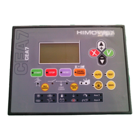
- Page 5 It also has keys that allow the user to control and program the control unit. Fig.1 CEA7 display module 1. Backlit display 4 lines by 20 digits. NOTE The display goes into low power mode (backlight off) after 10 minutes have passed without any keystroke.
- Page 6 2.1 CONTROL UNIT BUTTONS 2.1.3 DISPLAY BUTTONS Confirm (V). Enter the menus and confirm the data 2.1.1 BUTTONS FOR CONTROL UNIT OPERATING MODES entered. Cancel (X). Leave the menus and cancel the data entered. Automatic mode. The control unit monitors the status of the installa- Up (+).
- Page 7 2.2.2 ALARMS LEDS 2.3 PASSWORDS Fuel reserve The CEA7 control unit has 2 levels of 4-digit password to protect against unauthorized access. The different levels of access are as follows: Battery level • User (default password: 1111). User level access allows the operator to access the main menu of the CEA7 control unit.
-
Page 8: Operating Modes
3. OPERATING MODES Furthermore, activation of the network and genset contactors is performed by pressing the RED/MAINS and GROUP/GEN keys. 3.1 MANUAL MODE In manual mode, the control unit is commanded by the user via the front panel of In order to achieve activation of the genset contactor, the engine has to be the display module. -
Page 9: Test Mode
Programmable conditions for genset starting without activation of the genset 3.5 AUTOMATIC MODE LOCK contactor include: Pressing the Auto or Man keys for 5 seconds activates the locking of the mode. • (ESP1) Tariff warning (Settings table, parameter 7). This control unit state is indicated by the flashing of the mode key currently •... -
Page 10: Operation
4. OPERATION 4. Starting the engine (ARR). For a maximum time (Times table, parameter 5), the start output of the measurements module is activated while waiting to detect at least one of the programmed start conditions. The possible engine starting conditions are: •... - Page 11 7. Fumes control. The CEA7 control unit allows you to handle start-up in fumes PRACTICAL EXAMPLE OF A START OPERATION limitation mode by: • Assigning a programmable output (Settings table, parameter 1 to 4, NOTE value 97) that enables a fumes limitation system during the start-up...
- Page 12 If during the start cycle, the engine started condition is not detected, the ARR output deactivates and the corresponding LED turns off ( ). Subsequently the Once it has been detected that the engine is running the LED switches on ( ), control unit automatically attempts a new start, repeating a new cycle without the this indicates the end of the start cycle and the START button turns off.
-
Page 13: Engine Stop
4.2 ENGINE STOP PRACTICAL EXAMPLE OF A STOP OPERATION The engine stopping process in automatic mode is carried out as follows: NOTE 1. Cooling the engine. Once free of charging, the engine will continue running for It is advisable before starting the starting cycle that the general circuit breaker of the genset is in the OFF position. - Page 14 After concluding the cooling time (120 seconds by default), the PC output is The LED corresponding to the battery charging alternator voltage ( ) switches disabled or enabled according to the type of engine to carry out the stop, the on when the voltage provided by the battery charging alternator is below the set STOP button and the LED ( ) for the started engine switch off.
- Page 15 In case the response of the tank gauge is not linear, it is possible to program a tank gauge response curve of up to 8 points from the MenuParametersSen- It is possible to activate the fuel transfer pump of the CEA7 control unit by sors.
- Page 16 (Times table, parameter 27). The function of start The control unit configured in dynamo mode cannot use the voltage measured via up due to load demand is only enabled in Automatic mode of the CEA7 control unit. the DI analogue input for detecting an engine running condition.
- Page 17 The possible outputs that can be assigned to this function are: The CEA7 control unit allows to define up to 4 input sets depending on the value • The SC relay is assigned by default to this function. Furthermore, the SC of the digital inputs (Regulations table, parameters 38 to 41).
-
Page 18: Oil Pump Control
4.12 OIL PUMP CONTROL The CEA7 control unit allows to assign the oil pump control function to any programmable output of the control unit (value 131, Settings table, parameters 13 to 15, 22 to 23, 26 to 40). The oil pump control performs a sequence of 90 seconds of activation and 20 minutes of stop to the assigned output after 98,5 hours of running engine. - Page 19 5. CEA7 CONTROL UNIT INPUTS AND OUTPUTS The CEA7 control unit's digital inputs, both those with a specific purpose as well as those which are programmable, have a debounce time associated (Times table, parameters 15-24) which requires that the value of the input is stable over a time interval.
- Page 20 • OUT 2. Engine started (MA). • OUT 3. Programmable output 1 (SAL 1). The CEA7 control unit's measurements module has 5 digital inputs with operation that is already preset. • OUT 4. Battery charging alternator (D+). • OUT 5.
- Page 21 TARIFF WARNING SIGNAL (EJP1) The measurements module of the CEA7 control unit has 5 digital inputs (ENT1, This function is only managed in automatic mode of the CEA7 control unit. The ENT2, ENT3, ENT4, ENT5) which operation can be programmed. In addition, the...
- Page 22 TEST SIGNAL (TEST) There are 2 additional programmable alarms available (Settings table, parameters This function is only managed in automatic mode of the CEA7 control unit. 22 and 23) that can be associated with any of the programmable inputs and...
- Page 23 The analogue input P can be configured to operate as a digital input (Regulations table, parameter 35, value 1 or 2). 5.3 ANALOGUE INPUTS The CEA7 control unit has 5 analogue inputs for measuring the engine operation ENGINE INPUT TEMPERATURE (T) values. These analogue inputs characterize the operation of the engine to display its status and produce alarms if necessary.
- Page 24 PREHEATING OUTPUT. (PR). POWER OUTPUT ANALOGUE INPUTS EXPANSION The preheating output (PR) of the CEA7 control unit is an output connected to a The CEA7 control unit allows you to add 8 analogue temperature inputs to the high power shortable controller (70 A) which regulates the heating process of the PT100 sensor through the expansion of up to 2 CCPT100 devices.
- Page 25 The fuel transfer pump/heating output (BT) of the CEA7 control unit is a relay The engine stop output (ARR) of the CEA7 control unit is an output connected to output that can be configured (Regulations table, parameter 4) to manage the a high power shortable driver (40 A) which activates the stopping of the engine.
- Page 26 STARTED ENGINE OUTPUT (MA). DIGITAL OUTPUT • Programmable input 1. The started engine output (MA) of the CEA7 control unit is activated when any • Programmable input 2. started engine condition is detected and remains active while the engine is •...
- Page 27 7) including the cooling time during the stopping cycle. is detected (Thresholds table, parameter 32) during a set time (Times table, parameter 26). CEA7 CONTROL UNIT INPUTS AND OUTPUTS | PAGE 27...
- Page 28 5.8 EXTERNAL INPUTS Activation of the genset contactor is performed with a programmable time after The CEA7 control unit allows to assign external devices CCPT100 and CCIn8 detecting that the engine is in operation (Times table, parameter 6), it being...
- Page 29 6. CEA7 CONTROL UNIT ALARMS The CEA7 control unit has a list of alarms, the operation of which can be configured so that actions are performed or so that they are shown on the display module screen. The CEA7 control unit distinguishes between errors that cause the engine to stop (alarms) and errors do not cause the engine to stop (warnings).
- Page 30 NOTE EXAMPLES OF ALARM OPERATIONS • “EN” Alarm with engine stopped. Alarms that cause the engine to stop are not auto-resettable, they must be notified and reset so that the engine can be restarted, provided that the alarm • “AN” Warning that needs to be reset. does not remain active.
- Page 31 2. Pressing the RESET button eliminates the acoustic warning and the screen “AN” WARNING THAT NEEDS TO BE RESET, DOES NOT CAUSE THE ENGINE TO STOP stops flashing. The RESET LED remains lit and on the screen the alarm type is 1.
- Page 32 3. We provide solutions for the warning. In this case, we stop the engine if we 2. Pressing the RESET button eliminates the acoustic warning. The RESET LED believe this is necessary to detect the cause of the anomaly. Once the warning is remains LIT and the type of warning is shown on the display (which stops no longer active, "N"...
-
Page 33: List Of Alarms
Does not stop engine. Low genset power Warning Engine doesn't stop. Does not stop engine. Low fuel level by sensor Lit LED Warning Current asymmetry Warning Engine doesn't stop. Unexpected stop Stop failure CEA7 CONTROL UNIT ALARMS | PAGE 33... -
Page 34: Network Alarms
HIGH WATER TEMPERATURE There are 5 free programmable alarms that can be associated with engine The CEA7 control unit's high water temperature alarm is associated with the alarms and they can be reflected on the display via LEDS Aux1 and Aux2. - Page 35 LOW OIL PRESSURE BATTERY CHARGING ALTERNATOR FAILURE The CEA7 control unit's low oil pressure alarm is associated with the digital input The CEA7 control unit's battery charging failure alarm is associated with the specifically provided for low oil pressure (BPA). The status of this input must be analogue input for the battery charging alternator voltage (DI).
-
Page 36: Fuel Reserve
FUEL RESERVE The CEA7 control unit's under speed alarm is associated with the measurement The CEA7 control unit's fuel reserve alarm is associated with the digital input of the engine flywheel ring gear's rotation speed or through the J1939 channel of specifically provided for the fuel reserve (RC). - Page 37 MAXIMUM GENSET FREQUENCY GENSET VOLTAGE ASYMMETRY The CEA7 control unit's maximum genset frequency alarm is associated with the The CEA7 control unit's genset voltage asymmetry alarm is associated with the condition that the frequency generated by the genset is above the maximum condition that the difference between the measurements of RMS voltage in three- frequency limit set (Thresholds table, parameter 5).
- Page 38 LOW OIL PRESSURE BY SENSOR The CEA7 control unit's low oil pressure by sensor alarm is associated with the LOW BATTERY VOLTAGE analogue input for the oil pressure (T). The low oil pressure by sensor alarm is...
-
Page 39: High Battery Voltage
LOW FUEL LEVEL BY SENSOR The CEA7 control unit's high battery voltage alarm is activated when the battery The CEA7 control unit's low fuel level by sensor alarm is associated with the voltage measured is above a set limit (Thresholds table, parameter 36). - Page 40 STOP FAILURE • In a two-phase configuration voltage V12 is tested. The stop failure alarm of the CEA7 control unit goes off if after a time has • In a three-phase configuration with neutral or three-phase without elapsed (Times table, parameter 36) after the engine has been ordered to stop, neutral, phases V12, V23 and V13 are tested.
-
Page 41: Programmable Alarm
(ENT1, ENT2, ENT3, ENT4 or ENT5) or The CEA7 control unit's genset failure signal alarm is generated if no genset one of the engine alarm inputs (ATA, BPA or NA) in the J1939 option. The status voltage is detected during any phase while the engine is running. - Page 42 MAXIMUM NETWORK VOLTAGE The CEA7 control unit's programmable alarm 4 is activated associating the The CEA7 control unit's maximum network voltage alarm is associated with the operating mode of the programmable alarms (Settings table, parameter 22) to condition that the measurement of the network's RMS voltage is above the one of the general purpose digital inputs (ENT1, ENT2, ENT3, ENT4 or ENT5) or maximum voltage limit set (Thresholds table, parameter 13).
- Page 43 The detection of the maximum network frequency alarm can be configured MINIMUM NETWORK VOLTAGE (Alarms table, parameter 92) as follows: The CEA7 control unit's minimum network voltage alarm is associated with the • 0: Not checked. condition that the measurement of the network's RMS voltage is lower than the •...
- Page 44 NETWORK SIGNAL FAILURE ENT2, ENT3, ENT4 or ENT5) associated with the genset contactor confirmation The CEA7 control unit's network signal failure alarm is generated if network mode (Settings table, parameter 6) during a set time (Times table, parameter voltage is not detected in any phase.
- Page 45 The engine J1939 communication alarm verifies proper communication between programmable percentage (Thresholds table, parameter 38) of the nominal power the CEA7 control unit and the engine via the J1939 bus. This alarm is only set (Thresholds table, parameter 9) during a programmable interval of time available for control units which have the J1939 option installed.
-
Page 46: Idmt Alarm
EXPANSION when the genset current is below the overload current threshold. The CEA7 control unit’s high temperature alarm for PT100 probes 5 to 8 is The cooling time is determined by the formula: associated to the analogue inputs for PT100 temperature of the analogue input expansion. - Page 47 250 —programmable alarm 20) to delay the moment at which the alarm begins to confirm the alarm conditions. The CEA7 control unit’s high temperature alarm for PT100 level 2 probes 5 to 8 is associated to the analogue inputs for PT100 temperature of the analogue Programmable alarms 6 to 20 are set by default (Alarms table, parameters 185 input expansion.
- Page 48 257) to perform no action (warning). WATER IN FUEL (CEA7 VER469). The water in fuel alarm of the CEA7 control unit is associated to the detection of water in fuel by the control engine electronics and it is notified to the control unit through J1939 protocol.
-
Page 49: Maintenance
7. MAINTENANCE 7.1 OPERATION COUNTERS The CEA7 control unit records different accumulated readings related to control unit operation. The counters that record the control unit are: • Total operating hours counter. The control unit records the number of hours that the genset engine has been operating. The total operating hours counter is not resettable. -
Page 50: Maintenance Counters
7.3 LIST OF PREVIOUS ERRORS 7.2 MAINTENANCE COUNTERS The CEA7 control unit keeps a record of the detected alarms saving the status of the control unit when they occurred. The CEA7 control unit has 3 programmable counters that are loaded for a certain time which decreases while the engine is detected as running. - Page 51 In the event of an incorrect current reading when the genset is uncharged, it is The CEA7 control unit allows the use of nonlinear response gauges for measuring possible to perform a zero calibration (Table Measures, parameters 6, 8 and 10: fuel.
- Page 52 4. The first programmable fuel curve corresponds to the generator set's main fuel sensor. This curve is used for gauges with nonlinear responses that need more than 2 points for programming. If the CEA7 control unit detects a curve programmed in the first fuel curve, it cancels the parameters corresponding to the linear calibration of the generator set's main gauge (Measurements table, parameters 12 and 13).
- Page 53 8. OPTIONS New functions can be added to the CEA7 control unit using the CAN bus connection via expansion modules. 8.1 DISPLAY SCREEN (REPETITIVE) The control units CEA7 and CEM7 allow display screens to be added to the installation. This device displays the current status of the control unit, and if it is in automatic mode, can control the functioning of the genset.
- Page 54 • Error code. The CEA7 control unit allows connection of a J1939 device. The CCJ1939 device • Hours engine running when the error occurred. can monitor the following engine operating parameters depending on the •...
- Page 55 8.4 C2LAN 8.7 MODBUS CCRS485 The CEA7 control unit allows the connection of a C2Lan device for remote con- The CEA7 control unit allows connection of a C2Lan CCRS485 device for remote nection using TCP/IP connections. The C2Lan device allows the following: connection using RS485 connections over MODBUS protocol.
-
Page 56: Appendix I: Parameters Table
9. APPENDIX I: PARAMETERS TABLE The CEA7 control unit allows 3 levels of access for settings. To modify any of the CEA7 control unit’s parameters validation is required by entering the corresponding password. The 3 levels of access are: 1. User. Allows level 1 values to be read. (Default password: 1111). - Page 57 Tabla 1 Times Table Default Default Parameter Description Range Parameter Description Range value value Number of Starts. 1..10 Filtering of the ENT1 input. 1.0’’ 0.0’’.. 120.0’’ Time between Starts. Filtering of the ENT2 input. 1.0’’ 0.0’’.. 120.0’’ Period between starts during which all the outputs 5’’...
- Page 58 Tabla 3 Default Parameter Description Range Regulations Table value Default 0- Not programmed Parameter Description Range value 1- RC ALARM Input associated with the AUX1 LED on 2- BP ALARM 0- Off the display module. 3- AT ALARM 1- Manual 4- NA ALARM Fuel transfer pump operating mode.
- Page 59 Default Default Parameter Description Range Parameter Description Range value value 0- Unit panel Position of current measured. Value of inputs associated to Input Set 1. 1- Output line 0- Not permitted 1- Starting due to net- Value of inputs associated to Input Set 2. Management of forced operation.
- Page 60 Tabla 6 VDO: 323-803-001-008 VDO: 360-081-030-009 Thresholds Table SCANIA SCANIA Yanmar Yanmar Default Parameter PSW Description Range value VDO: 360-081-030-009 Programmable 1: 0- Three-phase without VOLVO VOLVO See curve table for neutral auxiliary sensor points Programmable 1 Programmable 2 1- Three-phase Three-phase, two-phase, single phase 2- Two-phase Programmable 1...
- Page 61 Default Default Parameter PSW Description Range Parameter PSW Description Range value value Maximum temperature level 2 of exter- Low engine temperature by sensor. OFF(0ºC)-40ºC 0-250 °C nal probe 6. Minimum heating temperature 25ºC 5 - 30 ºC Maximum temperature level 2 of exter- 0-250 °C nal probe 7.
- Page 62 Parameter PSW Description Default value Range Parameter PSW Description Default value Range Filter alarm 7 5’’ 0”…30” Filter alarm 17 5’’ 0”…30” Mode alarm 7 0..2 Mode alarm 17 0..2 Management alarm 8 Management alarm 18 0..4 0..4 Under Speed Low fuel level (by sensor) Filter alarm 8 15”...
- Page 63 Parameter PSW Description Default value Range Parameter PSW Description Default value Range Mode alarm 28 0..2 Mode alarm extension 3 0..2 0..1 Management alarm NFPA Management alarm C1 0. Not checked High battery voltage 0..4 Maximum NETWORK voltage 1. Checked and if an error (from version PHG6 v300) failure is detected the engine is...
- Page 64 Parameter PSW Description Default value Range Parameter PSW Description Default value Range Management alarm probe 1 Management alarm probe 8 Temperature probe 8 0..4 level 2 0..4 (from version PHG7 v457) Temperature probe 1 level 2 (from version PHG7 v420) Filter alarm probe 8 5’...
- Page 65 Parameter PSW Description Default value Range Parameter PSW Description Default value Range Programmable alarm 9 delay 0’ 0”…255” Programmable alarm 19 delay 0’ 0”…255” Programmable alarm 9 mode 0..2 Programmable alarm 19 mode 0..2 Programmable alarm 10 Programmable alarm 20 0..4 0..4 (from version PHG7 v458)
- Page 66 Tabla 8 Default Parameter PSW Description Range Settings Table (I/O) value See table 9 – Programmable control Default SC Programmable Output Mode Parameter PSW Description Range unit outputs value Input associated to preheating Programmable Output Mode 1 cut-off Programmable Output Mode 2 See table 9 –...
- Page 67 Tabla 9 Value Function Programmable control unit outputs 32..95 Unit alarm (see Table of Programmable output genset alarms allocation) Value Function Stabilized engine Not programmed Fumes control RC input Mains present BP input 99..130 Unit alarm (see Table of Programmable output genset alarms allocation) AT input YANMAR oil pump NA input...
- Page 68 Tabla 11 Valor Function Programmable output genset alarms allocation Extension ENT 1.7 (CCIn8 ID 0, input 7) (See Section 5.8) Index Alarm Water temperature Extension ENT 1.8 (CCIn8 ID 0, input 8) (See Section 5.8) Oil pressure Extension ENT 2.1 (CCPT100 or CCIn8 ID 1, input 1) (See Section 5.8) Emergency stop...
- Page 69 Tabla 12 Index Alarm Parameters clearance selector table Temperature probe 2 Temperature probe 3 Default Parameter PSW Description Range Temperature probe 4 value TEMPERATURE PROBE 1 Level 1 0- Three-phase without TEMPERATURE PROBE 2 Level 1 neutral 1- Three-phase TEMPERATURE PROBE 3 Level 1 2- Two-phase TEMPERATURE PROBE 4 Level 1 Signal type clearance 1...
- Page 70 Default Parameter PSW Description Default value Range Parameter PSW Description Range value Extension CCJ1939: Minimum network voltage clearance 1 SCANIA: 0.1: 1500 rpm Maximum network voltage clearance 1 2: 1800 rpm 3: idling speed Minimum network frequency clearance 1 VOLVO: Maximum network frequency clearance 1 Any writing switches speed between 1500 and 1800 rpm.
- Page 71 Tabla 14 Screen Table Parameter PSW Description Default value Range 0: Buzzer enabled Inhibition of buzzer 1: Buzzer disabled 0: Enable PD activation PD inhibition in inputs/outputs in I/O menu menu 1: Disable PD activation in I/O menu Enabling heating of display 0: Disabled heating of display (read-only parameter version DGT 1: Enabled heating of display...
-
Page 72: Appendix Ii. Cea7 Control Unit Screens
10. APPENDIX II. CEA7 CONTROL UNIT SCREENS 10.1 CONTROL UNIT STATUS The status of the CEA7 control unit is shown on the display, allowing access to different display options using the up and down navigation keys. • The current measurement display depends on the configuration of... - Page 73 2. Measurements of voltage between phases, currents each phase and 10.1.3 ENGINE STATUS SCREEN frequency. 1. Measurements of RPM., H., NC., DI., TM., VB., PA., display of engine speed RPM, H operating hours, NC fuel level, DI battery charging alternator voltage, TM NE T WO RK : 0 H z engine temperature, VB battery voltage, PA oil pressure.
- Page 74 Tabla 1 IA: Start inhibited. Regeneration functionality icon table AE: External start. CKG: Confirmation of genset contactor. DESCRIPCIÓN ICONO VALOR CKR: Confirmation of network contactor. DIESEL PARTICULATE FILTER K-: Relay activation loading. LAMP T: Test function. SPN: 3697 ON (blink). F: Forced operation function.
-
Page 75: List Of Errors
10.1.6 LIST OF ERRORS 10.1.8 DEVICE AUXILIARY ANALOGUE INPUTS (ONLY IF CCPT100 EXPANSION MODULE PROBES). A L A R M º MIN GENSET VOLTAGE º º Fig.1 Error reading Fig.1 E: Alarm / A: Warning CCPT100 analogue auxiliary inputs N: Pending notification º... -
Page 76: Control Unit Maintenance
10.2 CONTROL UNIT MAINTENANCE M E N U 7 . L a n g u a g e 8 . P a s s w o r d 10.2.1 PASSWORD ENTRY 9 1 9 3 9 With the control unit connected, select "Menu" and press . To enter the password using the cursor keys (+) and (-), select the number of the first digit and 1. - Page 77 A N A L O G U E I N P U T S NOTE The engine status screen only appears in those gensets that have the J1939 extension installed. The variables that appear displayed depend on the engine model installed. NC: Fuel level.
- Page 78 3. COUNTERS 4. LIST OF PREVIOUS ERRORS The second screen displaying J1939 measurements is available for firmware Once the previous errors menu has been selected we can select any of the versions 3.36 and higher for genset and automatic display modules. previous errors listed by pressing .
- Page 79 A R R The CEA7 control unit allows up to 5 different actions to be programmed on the same day of the week. For each option is activation range is defined indicating the hour and minute of the start and end; the start time must always be before Fig.3...
-
Page 80: Date And Time
If you wish to program an action with an operating range that covers 2 consecutive 7. LANGUAGE SELECTION days of the week (e.g. Monday between 22:00 and 03:00 on Tuesday), program To enter each menu select it with the cursors ▲▼ and press . the action to end at 23:59 on Monday and the same action to start at 00:00 on Tuesday. - Page 81 Using the arrow keys ▲▼the signal to be analysed is selected (VG1, VG2, VG3, 8. CUSTOMIZING PASSWORDS VR1, VR2, VR3, I1, I2 or I3). To display the harmonic press the key . * * * * P A S S W O R D * * * * >...
-
Page 82: Control Unit Programming
10.3 CONTROL UNIT PROGRAMMING V G 2 H 15 : To enter each menu select it with the cursors ▲▼ and press . H 17 : The main menu is restricted to a minimum of a maintenance level password. ... - Page 83 10.3.3 CUSTOMISING THE MANUFACTURER'S SCREEN M E A S U R E M E N T S P 0 1 From the programming texts option of the control unit it is possible to customise P 0 2 the manufacturer's screen. P 0 3 ...
- Page 84 If you want to finish programming the curve, hold down the key for 5 seconds 2 0 0 after entering the value for the physical units of the point; if you want to program 1 6 7 8 a new point on the curve, press the key . ...
-
Page 85: Access To Menus
10.3.7 LIST OF STARTS (ONLY EXPANSION CCJ1939) 10.4 ACCESS TO MENUS From the J1939 option it is possible to display the starts carried out from the MENU Associated External J1939 extension in standalone mode. Inputs/Outputs LIST OF STARTS Counters ... -
Page 86: Appendix Iii: Dimensions, Wiring And Mechanical Parts
11. APPENDIX III: DIMENSIONS, WIRING AND MECHANICAL PARTS 11.1 PHG7 MODULE INSTALLATION AND WIRING CURRENT Fig.2 PHG7 module wiring Fig.1 PHG7 module (APPENDIX III) DIMENSIONS, WIRING AND MECHANICAL PARTS | PAGE 86... - Page 87 Fig.3 PHG7 module wiring diagram WHEN BOTH MODULES ARE POWERED, VOLTAGE SUPPLY RANGE IS 8-33VCC. ATTENTION: RISK OF DAMAGE. (APPENDIX III) DIMENSIONS, WIRING AND MECHANICAL PARTS | PAGE 87...
-
Page 88: Inputs And Outputs
INPUTS AND OUTPUTS Signal Description Type Characteristics Analogue input with voltage Signal Description Type Characteristics Alternator voltage Input 0-40V Power supply Common analogue inputs Input VDO mass sensors Module supply voltage from 8 8÷36V Positive power supply Power supply to 36 V Digital outputs 1A -BAT Negative power supply... - Page 89 There are no special ventilation requirements due to the low power consumed by Signal Description Type Characteristics the control unit. Genset three-phase voltage input Analogue input for voltage The surface areas of the equipment and the external face should be cleaned with T-phase voltage Input measurement...
-
Page 90: Electrical Characteristics
ELECTRICAL CHARACTERISTICS Mini- Maxi- Symbol Parameter Conditions Typical Unit Mini- Maxi- Output current T = 1 s Symbol Parameter Conditions Typical Unit PNP outputs (D+, AL, MA, SAL1, SAL2, SAL3 terminals) Power supply (terminals 8÷36 V, –BAT, +BAT) Output voltage +BAT 8÷36 V Module supply voltage Output current +BAT... - Page 91 DIMENSIONS Fig.4 PHG7 module dimensions (APPENDIX III) DIMENSIONS, WIRING AND MECHANICAL PARTS | PAGE 91...
- Page 92 11.2 PHG7J MODULE INSTALLATION AND WIRING VOLTAGE FREE DIGITAL RELAY OUTPUT OUTPUTS Fig.6 PHG7J module wiring Fig.5 PHG7J module (APPENDIX III) DIMENSIONS, WIRING AND MECHANICAL PARTS | PAGE 92...
- Page 93 WHEN BOTH MODULES ARE POWERED, VOLTAGE SUPPLY RANGE IS 8-33VCC. ATTENTION: RISK OF DAMAGE. Fig.7 PHG7J module wiring diagram (APPENDIX III) DIMENSIONS, WIRING AND MECHANICAL PARTS | PAGE 93...
- Page 94 Signal Description Type Characteristics Signal Description Type Characteristics Power supply Digital outputs 1A Module supply voltage from 8 to Battery charging alternator Output PNP digital output 8÷36 V Positive power supply Power supply 36 V Alarm Output PNP digital output -BAT Negative power supply Power supply Module supply negative...
- Page 95 The control unit must be mounted at the front of an electrical panel, if possible in ELECTRICAL CHARACTERISTICS the centre to allow easy wiring. Symbol Parameter Conditions Minimum Typical Maximum Unit There are no special ventilation requirements due to the low power consumed by the control unit.
- Page 96 NOTE 1: Symbol Parameter Conditions Minimum Typical Maximum Unit Water temperature IP 65 on the front of the control unit when installed on the control panel with 4000 Ω resistance the sealing gasket provided. 4000 Ω The equipment has been designed and manufactured according to the require- ments of the directives and harmonized standards which are applicable for com- Power PNP outputs (terminals ARR, PR, PC) pliance with EC regulations.
- Page 97 DIMENSIONS 11.3 CEA7 MODULE Fig.2 CEA7 module INSTALLATION AND WIRING Fig.3 CEA7 module wiring Fig.1 PHG7J module dimensions (APPENDIX III) DIMENSIONS, WIRING AND MECHANICAL PARTS | PAGE 97...
- Page 98 To power the CEA7 device and make the other connections you should use a ca- ELECTRICAL CHARACTERISTICS ble with a section of 1 mm Mini- Typi- Maxi- Symbol Parameter Conditions Unit The CEA7 device is mounted on the front of an electrical panel. There are no special ventilation requirements due to the low power consumed by the device.
- Page 99 DIMENSIONS POWER SUPPLY Fig.4 CEA7 module dimensions. (APPENDIX III) DIMENSIONS, WIRING AND MECHANICAL PARTS | PAGE 99...
-
Page 100: Installation
11.4 SYMBOLS 11.5 GENERAL INFORMATION, CHARACTERISTICS AND INSTALLATION OF THE EQUIPMENT Warning. Consult the manufacturer's documentation. Consult the manufacturer's documentation. The following documentation is supplied with the equipment: 1. General information: Risk of electric shock. It is necessary to consult the documentation. 2. - Page 101 For proper protection of the equipment, the following elements must be installed in the electrical panel: Nº Fuses Amps General Positive Power CEA7 automatic digital control unit Phase U Phase V Phase W Differential Relay + Tripping Coil Battery Charger...
-
Page 102: Appendix Iv: Can Communications
12. APPENDIX IV: CAN COMMUNICATIONS 12.1 INTRODUCTION The CAN BUS, is an industrial bus characterized by great strength and reliability and ensures proper communication between the devices in noisy environments. Devices with CAN controller can be integrated into an industrial automation and control system. - Page 103 NOTE Tabla 2 The existing impedance must be measured when all the equipment is no longer working Characteristics of the cable depending on the number of nodes or does not have physical access to the network. For more information, please see the Length of bus Number of nodes ISO 11898 specification and the different notes that apply in this respect.
- Page 104 12.4 WIRING DIAGRAMS MEASUREMENTS USBCan MEASUREMENTS DISPLAY Fig.6 Manual / automatic control unit + CCrs option Fig.3 Manual / automatic control unit MANUAL SWITCHING MANUAL SWITCHING MEASUREMENTS MEASUREMENTS MEASUREMENTS MEASUREMENTS DISPLAY DISPLAY DISPLAY DISPLAY Fig.4 CCrs Manual control unit + switching MEASUREMENTS CCrs Fig.7...
-
Page 105: Appendix V: Calibration Of The Control Unit
. Calibration of the system can be reset the network (only control units CEA7 and CEC7). To carry out this process, the by writing parameter 17 for the network voltage and parameter 18 for the genset enabling of a manufacturer level password is required. -
Page 106: Appendix Vi: Expanding Inputs
APPENDIX VI: EXPANDING INPUTS 14. APPENDIX VII: COMMUNICATIONS FAILURE The CEA7 control unit allows you to add digital inputs, analogue inputs (0-10 V, 4-20 mA and resistant) and PT100 by connecting input expansion module devices The user interface of the CEA7 control unit displays the text COMMUNICATIONS (CCIn8 and CCPT100) to the control unit's communications bus. - Page 107 Fax +34 968 19 12 17 | Export Fax +34 968 33 43 03 www.himoinsa.com HIMOINSA reserves the right to modify any characteristic without prior notice. Illustrations may include optional equipment and/or accessories. Non contractual images. The technical information described in this manual corresponds to the information available at the time of printing.
Need help?
Do you have a question about the CEA7 and is the answer not in the manual?
Questions and answers