Advertisement
Table of Contents
- 1 Table of Contents
- 2 Introduction
- 3 Front of the Display Module
- 4 Operating Modes
- 5 Connecting to the Generator Set
- 6 Operation
- 7 CEC7 Control Unit Inputs and Outputs
- 8 CEC7 Control Unit Alarms
- 9 Maintenance
- 10 Options
- 11 Appendix I: Parameters Table
- 12 Appendix II: CEC7 Control Unit Screens
- 13 Appendix III: Synchronization
- 14 Appendix IV: Dimensions, Wiring, Mechanical Parts and Electrical Characteristics
- 15 Appendix V: CEC Communications
- 16 Appendix VI: Calibration of the Control Unit
- Download this manual
Advertisement
Table of Contents

Subscribe to Our Youtube Channel
Related Manuals for Himoinsa CEC7


Summary of Contents for Himoinsa CEC7
- Page 1 INSTRUCTION MANUAL PROFESSIONAL CEC7 DIGITAL SWITCHING CONTROL UNIT...
-
Page 2: Table Of Contents
1. Introduction 2. Front of the display module 3. Operating modes 4. Connecting to the generator set 5. Operation 6. CEC7 control unit inputs and outputs 7. CEC7 control unit alarms 8. Maintenance 9. Options 10. Appendix I: parameters table 11. -
Page 3: Introduction
1. INTRODUCTION The CEC7 control unit is an electric network signal supervision device and conducts supervision and control of power supply through the generator set. The control unit consists of 2 different modules: • Display module. The display module is responsible for carrying out the information tasks regarding the status of the device and allows actions to be performed by the user;... - Page 4 The following additional modules can be added as options via the CAN bus: 1.1 MEASUREMENTS MODULE • CAN/USB. The measurements module provides the following electrical signal characteristics, • C2CLOUD (GPRS and eet manager). both those generated and those from the network itself: •...
-
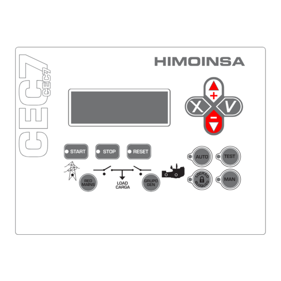
Page 5: Front Of The Display Module
It also has keys that allow the user to control and program the control unit. Fig.1 CEC7 display module 1. Backlit display with 4 lines of 20 digits. NOTE The display goes into low power mode (backlight off) after 10 minutes without any button being pressed. - Page 6 2.1 CONTROL UNIT BUTTONS 2.1.3. DISPLAY BUTTONS Confirm (V). Enter the menus and con rm the data 2.1.1. BUTTONS FOR CONTROL UNIT OPERATING MODES entered. Cancel (X). Leave the menus and cancel the data entered. Automatic mode. The control unit monitors the status of the installa- Up (+).
- Page 7 AC electric signal 2.3 PASSWORDS The CEC7 control unit has 2 levels of 4-digit password to protect against unauthorized access. The different levels of access are as follows: • User (default password: 1111). User level access allows the operator to access the main menu of the CEC7 control unit.
-
Page 8: Operating Modes
3. OPERATING MODES 3.1 MANUAL MODE In manual mode, the control unit is commanded by the user via the front panel of the display module. The user can start and stop the engine by pressing the START and STOP keys respectively. Pressing the START key initiates the engine starting procedure (without deactivating the network contactor). - Page 9 Furthermore, activation of the network and genset contactors is performed by 3.4 LOCKED MODE pressing the RED/MAINS and GROUP/GEN keys. In Lock mode , the control unit disables the genset startup under any condition. 3.5 AUTOMATIC MODE LOCK In order to achieve activation of the genset contactor, the engine has to be Pressing the AUTO or MAN keys for 5 seconds activates the mode lock.
-
Page 10: Connecting To The Generator Set
The integrated control mode on the generator set is programmed in the CEC7 control unit (Regulations table, parameter 30, values 0 and 1). - Page 11 The genset signal drop condition causes the genset contactor to open. The external control mode on the generator set is programmed in the CEC7 con- trol unit (Regulations table, parameter 30, value 3).
-
Page 12: Operation
3. Start-up of the generator set. The CEC7 control unit commands the start-up of the generator set: • Via the LT breaker in CEC7 control units con gured in external mode. • Via the communications bus in CEC7 control units con gured in integrated mode with CEM7 control units. - Page 13 The generator set will start operating, providing the power supply to the • Via the LT breaker in CEC7 control units con gured in external mode. installation, when network power consumption is detected which is more than • Via the communications bus in CEC7 control units con gured in the limit set by parameter (Threshold table, parameter 34).
- Page 14 This function makes it possible to assign to a programmable input of the CEC7 The CEC7 control unit makes it possible to avoid the zero in the power supply control unit the ability to stop the activation of the genset contactor. In this way, upon the return of the network via the Second Zero (SZ7) expansion.
- Page 15 5.8 TIMER. The CEC7 control unit has a timer that tells the control device the current time and date. This device allows the weekly programming of: • Scheduled start-ups. • Scheduled locks. • Scheduled engine tests and maintenance. • Energy counters (day, month, year).
-
Page 16: Cec7 Control Unit Inputs And Outputs
(Times table, parameters 22 to 24) which requires that the value of the input is stable over a time interval. Also, the CEC7 control unit's inputs can be con gured to be active with contact closed to earth or be inactive with contact closed to earth (Regulations table parameters 11 to 14). - Page 17 Enabling of genset contactor activation (HKG) This function is only managed in automatic mode of the CEC7 control unit. The input con gured as enabling genset contactor activation (Settings table, parameter 8) inhibits the activation of the genset contactor until the input is active after stabilization of the genset electrical signal.
- Page 18 Network contactor output (CR) - Relay output Neutral to earth switch output. The network contactor output (CR) of the CEC7 control unit is a relay output that The earth switch output of the CEC7 control unit is assigned to the SC relay manages the closing and opening of the network contactor.
-
Page 19: Cec7 Control Unit Alarms
7. CEC7 CONTROL UNIT ALARMS The CEC7 control unit has a list of alarms, the operation of which can be con gured so that actions are performed or so that they are shown on the display module screen. The CEC7 control unit, working with a generator set control unit from the CEM7... - Page 20 2. Pressing the RESET button eliminates the acoustic warning and the screen stops ashing. The RESET LED remains lit and on the screen the alarm type is displayed. Example: Alarm active “EN” High Water Temperature. (2) ALARM HIGH WATER TEMPERATURE Fig.2 CEC7 CONTROL UNIT ALARMS | PAGE 20...
- Page 21 1. Upon detection of an alarm or warning, the control unit produces an acoustic RESET button. (6) signal, the LED of the RESET button and the screen ashes and the alarm digital output (AL) is activated.(4) WARNING HIGH WATER TEMPERATURE Fig.6 Fig.4 CEC7 CONTROL UNIT ALARMS | PAGE 21...
- Page 22 NETWORK sequence failure Alarm started. of the default programming and the alarm corresponding to the network Checked and if an error is detected the engine is NETWORK signal drop failure Alarm thresholds. started. CEC7 CONTROL UNIT ALARMS | PAGE 22...
- Page 23 7.1.4. PROGRAMMABLE WARNINGS GENSET VOLTAGE ASYMMETRY The CEC7 control unit has a function that allows the noti cation of up to 4 The CEC7 control unit's genset voltage asymmetry alarm is associated with the warnings that do not generate the stopping of the genset. This function is only...
- Page 24 MAXIMUM GENSET FREQUENCY MINIMUM GENSET VOLTAGE The CEC7 control unit's maximum genset frequency alarm is associated with the The CEC7 control unit's minimum genset voltage alarm is associated with the condition that the frequency generated by the genset is above the maximum condition that the measurement of the genset's RMS voltage is less than the frequency limit set (Thresholds table, parameter 5).
- Page 25 The detection of the maximum network voltage alarm can be con gured (Alarms STOP FAILURE table, parameter 88) as follows: The CEC7 control unit’s stop failure alarm is generated if 90 seconds have • 0: Not checked. elapsed after ordering the engine to stop and not all the stopped engine condi- •...
- Page 26 NETWORK SIGNAL FAILURE The CEC7 control unit's network signal failure alarm is generated if network MINIMUM NETWORK FREQUENCY voltage is not detected in any phase. The CEC7 control unit's minimum network frequency alarm is associated with the...
- Page 27 PROGRAMMABLE ALARM 3 The CEC7 control unit's network contactor switching failure alarm is generated Programmable alarm 3 on the CEC7 display is activated associating any of the when the network contactor is activated through the CR relay of the measurements...
-
Page 28: Maintenance
8. MAINTENANCE 8.1 LIST OF PREVIOUS ERRORS The CEC7 control unit keeps a record of the detected alarms saving the status of the control unit when they occurred. The CEC7 control unit stores the last 100 errors detected. 8.2 LIST OF EQUIPMENT 8.2.1. - Page 29 NOTE The existence of modules with the same ID is not permitted. If during start up a display module detects another analogue module with the same ID, the message will be displayed ERROR ID. DISPLAY. NOTE By changing the ID of a module, it automatically restarts. It is important to NOT change the ID of measurements modules with the genset in operation.
-
Page 30: Options
9. OPTIONS New functions can be added to the CEC7 control unit using the CAN bus connection via expansion modules. 9.1 TELESIGNAL The CEC7 control unit allows connection of a Telesignal device. The Telesignal device has 12 relay outputs (4 with NO and NC contact, 8 with NO contact). - Page 31 9.2 C2LAN 9.5 CCRS232 The CEC7 control unit allows the connection of a C2Lan device for remote The CEC7 control unit allows the connection of a CCRS232 device together with connection using TCP/IP connections. The C2Lan device allows the following: a MODEM RTB or GPRS for remote connection or management via SMS messages using telephone network connections.
-
Page 32: Appendix I: Parameters Table
10. APPENDIX I: PARAMETERS TABLE The CEC7 control unit allows 3 levels of access for settings. To modify any of the CEC7 control unit's parameters validation is required by entering the correspond- ing password. The 3 levels of access are: 1. - Page 33 Tabla 1 Tabla 3 Times table Regulations table Default Default Parameter Description Range Parameter Description Range value value Start Delay. 0- Locked 0’’ 0’’..1800’’ Time between power failure and engine start. 1- Manual Default Starting Mode. 2- Automatic Charging Activation Time. 3- Test Time from the moment the starting of the engine is 3’’...
- Page 34 Tabla 4 Parameter Psw Description Default value Range Thresholds table Management unit commutation alarm 5 0..4 Default Maximum Unit Frequency alarm. Parameter Psw Description Range value Filter unit commutation alarm 5 0”…30” 0- Three-phase Maximum Unit Frequency alarm. without Management unit commutation alarm 6 0..4 neutral Phase sequence alarm.
- Page 35 Parameter Psw Description Default value Range Parameter Psw Description Default value Range 0. Not checked Maximum synchronisation wait time. 0..300” 1. Checked and if an Management alarm C8 error is detected the CR commutation failure. genset is stopped with 0- does not allow cooling power failure Synch alarm action.
- Page 36 Parameter Psw Description Default value Range Heater integral coef cient 0..255 Heater proportional coef cient 0..255 Heater target temperature 0..10 Contrast 0..255 (APPENDIX I) PARAMETERS TABLE | PAGE 36...
-
Page 37: Appendix Ii: Cec7 Control Unit Screens
11. APPENDIX II: CEC7 CONTROL UNIT SCREENS 11.1 CONTROL UNIT STATUS The status of the CEC7 control unit is shown on the display screen, allowing access to different display options using the up and down navigation keys. • The current measurement display depends on the con guration of the current measurement transformers position (Regulations table, parameter 24). - Page 38 the phase currents and frequency. These voltage measurements are made by the 3. Measurements of genset voltage (V), genset current (A), fuel level (NC), engine power module of the transfer switch controller (PHR7). speed (RPM) and genset power (P). NETWORK: GENERATOR: V 1 2 2 3 0 V...
- Page 39 2. Measurements of the total energy consumed in the Day, Month and Year. 11.1.4. CONTROL UNIT STATUS SCREEN 1. Status of the programmable inputs. E N E R G Y : 3 0 k W h G E N S E T : S T O P P E D 1 0 K W h C K G ü...
- Page 40 11.2 CONTROL UNIT MAINTENANCE MENU à 4 . History . Schedule 11.2.1. PASSWORD ENTRY . Date / Time With the control unit connected, select "Menu" and press ü. To enter the password using the cursor keys (+) and (-), select the number of the rst digit and à...
- Page 41 2. COUNTERS 3. LIST OF PREVIOUS ERRORS The second screen displaying J1939 measurements is available for rmware Once the previous errors menu has been selected we can select any of the versions 3.36 and higher for genset and automatic display modules. previous errors listed by pressing ü.
- Page 42 • Free (----): no action is scheduled for that range; the start time and end Periodicity. time have no effect. The CEC7 control unit allows up to 5 different actions to be programmed on the * * * * * * * * * * same day of the week.
- Page 43 If you wish to program an action with an operating range that covers 2 consecutive 6. LANGUAGE SELECTION days of the week (e.g. Monday between 22:00 and 03:00 on Tuesday), program To enter each menu select it with the cursors ▲▼ and press ü. the action to end at 23:59 on Monday and the same action to start at 00:00 on Tuesday.
- Page 44 7. CUSTOMIZING PASSWORDS V G 2 * * * * PASSWORD * * * * p H 5 à 0 User q H 7 T H D Maintenance V G 3 * * * * USER * * * * p H 5 Password 1 1 1 1...
- Page 45 PARAMETERS V G 2 à 7 . Texts . Equipment list p H 5 . Selector q H 7 T H D PARAMETERS Con rm key (ü). à 10 . p 11 . V G 2 q 12 . Sensors p H 11 : PARAMETERS q H 13 :...
- Page 46 11.3.1. CUSTOMISING THE PROGRAMMABLE ALARMS TEXT 11.4 ACCESS TO MENUS We can associate a text to the programmable inputs, maximum 15 characters. CEC7 MENU The control unit has an alphabet A-Z and numbers 0-9. Associated External Inputs/Outputs ü ü ü...
-
Page 47: Appendix Iii: Synchronization
12.1 PROCEDURE The synchronization process is performed both during start-up of the genset as well as the return of the network provided that the CEC7 control unit is in AUTO or TEST mode.During the synchronization process the CEC7 control unit acts using the Second Zero expansion controlling: •... - Page 48 In the case of failure to achieve synchronization for a maximum programmable enabling of the load transfer in synchronization: time (Synchronization table parameter 7), the CEC7 control unit depending on its • If the synchronized load transfer is disabled (Synchronization table,...
- Page 49 The adjustment of generator set con gurations is performed from the * * * * SYNCHRONIZATION * * * * Maintenance menuàSynchronization of the CEC7 control unit. In this menu it is à 1 . A d j u s t m e n t 3 8 2 V possible to perform maintenance both with regards the regulation of voltage as .
- Page 50 7. Select the value 1 from the menu MaintenanceàSynchronizationàFrequency àAdjustment. 12.3.2. SYNCHRONIZATION COEFFICIENTS 8. The genset frequency signal must be less selecting the value 1 from the menu The response of the CEC7 control unit depends on the Synchronization MaintenanceàSynchronizationàFrequencyàAdjustment than selecting coef cients (PID) both in terms of the adjustment of amplitude and the value 0.
- Page 51 à 3 . PID and genset of the CEC7 control unit. To perform the synchronization veri cation process, the following is required: • Stable motor. • Stable network signal.
- Page 52 * * * * AMPLITUDE à 2 . TEST . PID Fig.2 Network/genset signal deviation (‰): Flashing-Deviation above threshold permitted / Lit- Deviation below threshold permitted (APPENDIX III) SYNCHRONIZATION| PAGE 52...
-
Page 53: Appendix Iv: Dimensions, Wiring, Mechanical Parts And Electrical Characteristics
13. APPENDIX IV: DIMENSIONS, WIRING, MECHANICAL PARTS AND ELECTRICAL CHARACTERISTICS 13.1 PHR7 MEASUREMENTS MODULE INSTALLATION AND WIRING Fig.2 PHR7 module wiring Fig.1 PHR7 module (APPENDIX IV) DIMENSIONS, WIRING AND MECHANICAL PARTS | PAGE 53... - Page 54 WHEN BOTH MODULES ARE POWERED, VOLTAGE SUPPLY RANGE IS 8-33VCC. ATTENTION: RISK OF DAMAGE. Fig.3 PHR7 module wiring diagram (APPENDIX IV) DIMENSIONS, WIRING AND MECHANICAL PARTS | PAGE 54...
- Page 55 INPUTS AND OUTPUTS Signal Description Type Characteristics Signal Description Type Characteristics Power supply Voltage free relay outputs 8÷36V Positive power supply Power supply Module supply voltage from 8 to 36 V C network breaker Output Voltage free relay output -BAT Negative power supply Power supply Module supply negative...
- Page 56 The disconnecting means must be accessible by the user. The negative terminal ELECTRICAL CHARACTERISTICS of the battery, the chassis of the electrical panel and the chassis of the genera- Mini- Maxi- Symbol Parameter Conditions Typical Unit tor set must all be earthed. The manufacturer is not liable for any damage caused by not following the warn- Power supply (terminals 8÷36 V, –BAT, +BAT) ings and / or recommendations indicated in the manual, since the protection en-...
- Page 57 DIMENSIONS Mini- Maxi- Symbol Parameter Conditions Typical Unit Voltage-free relay outputs (BTC, BTNA terminals) High voltage relay contacts Current relay contacts cosf = 1 Environmental conditions and protection of the enclosure Operating temperature ºC No conden- Relative humidity sation IP Degree of Protection *see note 1 NOTE 1: IP 65 on the front of the control unit when installed on the control panel with...
- Page 58 INSTALLATION AND WIRING 13.2 CEC7 MODULE To power the CEC7 device and make the other connections you should use a ca- ble with a section of 1 mm The CEC7 device is mounted on the front of an electrical panel. There are no special ventilation requirements due to the low power consumed by the device.
- Page 59 INPUTS AND OUTPUTS Mini- Maxi- Symbol Parameter Conditions Typical Unit SIGNAL DESCRIPTION TYPE CHARACTERISTICS Low level input current VIN = 0 V High level input current VIN = 12 V POWER SUPPLY 8÷33 V Positive battery Power supply Module supply voltage Environmental conditions and protection of the enclosure terminal from 8 to 33 V Operating temperature...
- Page 60 DIMENSIONS Fig.3 CEC7 module dimensions. (APPENDIX IV) DIMENSIONS, WIRING AND MECHANICAL PARTS | PAGE 60...
- Page 61 13.3 SYMBOLS 13.4 GENERAL INFORMATION, CHARACTERISTICS AND INSTALLATION OF THE EQUIPMENT Warning. Consult the manufacturer's documentation. Consult the manufacturer's documentation. The following documentation is supplied with the equipment: 1. General information: Risk of electric shock. It is necessary to consult the documentation. 2.
- Page 62 For proper protection of the equipment, the following elements must be installed in the electrical panel: Nº FUSES AMPS General Positive Power Digital Automatic Control Unit CEC7 Phase U Phase V Phase W Differential Relay + Tripping Coil Battery Charger The negative terminal of the battery, the chassis of the electrical panel and the chassis of the generator set must all be earthed.
-
Page 63: Appendix V: Cec Communications
14. APPENDIX V: CAN COMMUNICATIONS 14.1 INTRODUCTION The CAN BUS is an industrial bus characterized by great strength and reliability and ensures proper communication between the devices in noisy environments. Devices with CAN controller can be integrated into an industrial automation and control system. - Page 64 NOTE Tabla 2 The existing impedance must be measured when all the equipment is no longer working Characteristics of the cable depending on the number of nodes or does not have physical access to the network. For more information, please see the Length of bus Number of nodes ISO 11898 speci cation and the different notes that apply in this respect.
- Page 65 14.4 WIRING DIAGRAMS MANUAL SWITCHING MANUAL SWITCHING MEASUREMENTS MEASUREMENTS MEASUREMENTS MEASUREMENTS DISPLAY DISPLAY DISPLAY DISPLAY Fig.3 Manual / automatic control unit CCrs MEASUREMENTS CCrs Fig.6 Manual control unit + switching + CCrs DISPLAY Fig.4 Manual control unit + switching MEASUREMENTS USBCan DISPLAY Fig.5...
-
Page 66: Appendix Vi: Calibration Of The Control Unit
3, 4 and 5 for calibrating the voltages R, S and T of the genset. Also, parameters 14, 15 and 16 are enabled for calibrating the voltages U, V and W of the network (only control units CEA7 and CEC7). To carry out this process, ü... - Page 67 Fax +34 968 19 12 17 | Export Fax +34 968 33 43 03 www.himoinsa.com HIMOINSA reserves the right to modify any characteristic without prior notice. Illustrations may include optional equipment and/or accessories. Non contractual images. The technical information described in this manual corresponds to the information available at the time of printing.
Need help?
Do you have a question about the CEC7 and is the answer not in the manual?
Questions and answers