Sign In
Upload
Manuals
Brands
Himoinsa Manuals
Control Unit
CEM7
Himoinsa CEM7 Manuals
Manuals and User Guides for Himoinsa CEM7. We have
2
Himoinsa CEM7 manuals available for free PDF download: Instruction Manual
Himoinsa CEM7 Instruction Manual (99 pages)
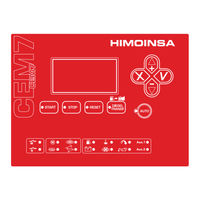
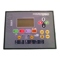
Digital control unit
Brand:
Himoinsa
| Category:
Control Unit
| Size: 4 MB
Table of Contents
Table of Contents
2
Introduction
3
Measurements Module
4
Front of the Display Module
6
Backlit Display 4 Lines by 20 Digits
7
Buttons for Control Unit Operating Modes
7
Control Unit Command Buttons
7
Control Unit Buttons
7
Contactor Buttons (Only Cem7P Module)
8
Status Leds
8
Engine Status Leds
8
Alarms Leds
8
Passwords
9
Manual Mode
10
Operating Modes
10
Automatic Mode
11
Mode Locking Function
11
Starting the Engine
12
Diesel Engine
12
Operation
12
Gas Engine
13
Starting the Motor (ARR)
13
Practical Example of a Start Operation
14
Engine Stop
16
Practical Example of a Stop Operation
17
Fuel Transfer Pump
18
Heating
19
Battery Charging Alternator
19
Alternator Mode
19
Programming
20
Dynamo Mode
20
Start/Stop Key
20
Start Due to Load Demand (Only Cea7Cc2 Expansion)
20
Genset in Reserve
21
Motorpump Mode
21
CEM7 Control Unit Inputs and Outputs
22
Digital Inputs
23
High Temperature (Ata)
23
Low Oil Pressure (Bpa)
23
Water Level (Na)
23
Programmable Inputs
24
Tariff Warning Signal (Ejp1)
24
Tariff Change Signal (Ejp2)
24
Disabling Start up Signal (Ia + Ent5)
24
Selection of Set of Parameters (S1 and S2)
25
Verification of Gas Ramp (S1 and S2)
25
Programmable Alarms (Al4 and Al5)
25
Programmable Alarms (Al1, Al2 and Al3)
25
Auxiliary Analogue Input (Aa)
26
Oil Pressure Input (P)
26
Engine Input Temperature (T)
26
Alternator Voltage Input (DI)
26
Programmed Digital Outputs
27
Preheating Output. (Pr). Power Output
27
Engine Starting Output. (Arr). Power Output
27
Engine Stop Output. (Pc). Power Output
27
Alarm Output (Al). Digital Output
28
Started Engine Output (Ma). Digital Output
28
Electronic Protection Output (Sc). Digital Output
28
Inhibited Output
28
Programmed Output for Dummy Load
29
Programmed Output for Alarm
29
Programmed Output for Mode
29
Programmed Output for Function
29
Programmed Output for Genset/Network Contactor State (Only Cea7)
30
Watchdog Programmed Output
30
Stabilized Engine Programmed Output
30
Programmed Fumes Control Output
30
CEM7 Control Unit Alarms
31
“En” Alarm with Engine Stopped
32
“A” Auto-Resettable Warning
34
List of Alarms
35
Alarms Associated with Programmable Inputs
35
Engine Alarms
35
Generator Alarms
35
Description of the Alarms
36
High Water Temperature
36
Low Oil Pressure
36
Emergency Stop (Action Not Programmable)
37
Battery Charging Alternator Failure
37
Starting Failure
37
Low Water Level
37
Overload
38
Under Speed
38
Overspeeding
38
Fuel Reserve
38
Genset Voltage Asymmetry
39
Maximum Genset Voltage
39
Maximum Genset Frequency
39
Incorrect Genset Phases Sequence
39
Reverse Power
40
Low Battery Voltage
40
High Water Temperature by Sensor
40
Low Oil Pressure by Sensor
40
High Battery Voltage
41
Low Battery Voltage When Starting
41
Low Auxiliary Battery Voltage
41
Low Fuel Level by Sensor
41
Short Circuit
42
Minimum Genset Voltage
42
Minimum Genset Frequency
42
Unexpected Stop
42
Low Engine Temperature
43
Genset Signal Failure
43
Genset Contactor Switching Failure (Cem7 Ver455 /Phg7 Ver407
44
Genset Power Alarm (Cem7 Ver460 / Phg7 Ver 4.19 or Higher)
45
Engine J1939 Communication
45
Idmt Alarm
46
Example Calculation of the Idmt Curve Time Constant (T)
46
Operation Counters
47
Maintenance
47
Maintenance Counters
48
List of Previous Errors
48
List of Equipment
48
Information on the List of Equipment
48
Allocation of Ids
49
Resetting the Current Measurements
49
Programming Analogue Sensors Curve
49
Programming the Gauge Response Curve
50
Display Screen (Repetitive)
51
Options (Expansions)
51
Timer
52
Installation on the Display Module
52
Telesignal
52
Ccj1939/Cem7J
53
CC/Lan
54
Second Zero Suppression
54
Announcement Panel
54
Modbus CC/Lan
54
Analogue Inputs Expansion Pt100
55
Precision Gauge Expansion
55
Snmp Cclan
55
Appendix I: Parameters Table
56
Times Table
57
Measurements Table
57
Regulations Table
58
Analogue Sensors
59
Point Curve of Auxiliary Sensor VDO 323-801-012-00
59
Thresholds Table
59
Alarms Table
60
Settings Table (I/O)
63
Settings Table (I/O). Extension from Version Phg6/7V250
63
Programmable Output Genset Alarms Allocation
64
Parameters Clearance Selector Table
64
Screen Table
65
Table J1939
65
Control Unit Status
66
Generator Measurement Screens
66
Appendix II. CEM7 Control Unit Screens
66
Engine Status Screen
67
Control Unit Status Screen
67
Status of the Programmable Inputs
67
Power and Energy Screen
67
List of Errors
68
Control Unit Maintenance
68
Password Entry
68
Inputs and Outputs Display
69
Main Menu
69
Engine Status Display (Only Ccj1939 Expansion or Cem7J Option)
70
Counters
70
Analogue Inputs
70
Schedule
71
Date and Time
73
Language Selection
73
Customizing Passwords
73
Synchronization
74
Harmonics
74
Control Unit Programming
75
Texts
75
Screen
76
Customising the Manufacturer's Screen
76
Programming Sensor Curves
76
List of Errors J1939
77
List of Starts (Only Expansion Ccj1939)
78
Access to Menus
78
Measurements Module Phg7
79
Appendix III: Dimensions, Wiring and Mechanical Parts
79
Measurements Module Wiring PHG7
81
Electrical Characteristics
82
Display Module Cem7
83
Display Module Wiring
83
Measurements Module Phg7J
85
Measurements Module Wiring PHG7J
87
Display Module: Cem7.1
89
Display Module Wiring CEM7.1
90
General Information, Characteristics and Installation of Equipment
91
Appendix IV: CAN Communications
92
Wiring
93
Characteristics of the Cable Depending on the Length
93
Characteristics of the Cable Depending on the Number of Nodes
93
Wiring Diagrams
94
Appendix V: Calibration of the Control Unit
95
Appendix VI: Expanding Inputs
97
Appendix VII: Communications Failure
97
Advertisement
Himoinsa CEM7 Instruction Manual (107 pages)
DIGITAL CONTROL UNIT
Brand:
Himoinsa
| Category:
Control Unit
| Size: 3 MB
Table of Contents
Operating Modes
8
Manual Mode
8
Automatic Mode
8
Test Mode
9
Locked Mode
9
Operation
10
Starting the Engine
10
Engine Stop
13
Oil Pump Control
18
List of Alarms
33
Engine Alarms
33
Network Alarms
34
Description of Alarms
34
High Water Temperature
34
Fuel Reserve
36
High Battery Voltage
39
Programmable Alarm
41
Idmt Alarm
46
Maintenance
49
Operation Counters
49
Maintenance Counters
50
List of Equipment
50
Appendix I: Parameters Table
56
Appendix II. Cea7 Control Unit Screens
72
List of Errors
75
Control Unit Maintenance
76
Password Entry
76
Date and Time
80
Language Selection
80
Control Unit Programming
82
Access to Menus
85
Appendix III: Dimensions, Wiring and Mechanical Parts
86
Installation and Wiring
86
Inputs and Outputs
88
Electrical Characteristics
90
Installation
100
Appendix IV: Can Communications
102
Appendix V: Calibration of the Control Unit
105
Appendix VI: Expanding Inputs
106
Appendix VII: Communications Failure
106
Advertisement
Related Products
Himoinsa CEM7.2
Himoinsa CEC7
Himoinsa CEA7
Himoinsa CEM7G
Himoinsa M1
Himoinsa M6
Himoinsa Categories
Control Unit
Portable Generator
Lighting Equipment
More Himoinsa Manuals
Login
Sign In
OR
Sign in with Facebook
Sign in with Google
Upload manual
Upload from disk
Upload from URL