Advertisement
Quick Links
Advertisement

Related Manuals for Himoinsa M6


Summary of Contents for Himoinsa M6
- Page 1 INSTRUCTION MANUAL PROFESIONAL M6 CONTROL UNIT...
- Page 2 INDEX 1. Introduction 2. Front of the control unit 3. Connections 4. Operation 5. Dimensions, wiring and mechanical parts 6. Table of parameters | PAG. 2...
- Page 3 1. INTRODUCTION The M6 control unit is an electronic monitoring, control and protection controller for generator sets. The general characteristics are as described below: 1. Supply voltage 8/36V. 2. Start and mode selection key. • “AUTO” mode. Start activated through an external start input via volt free contact ( LT) •...
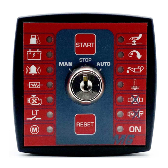
- Page 4 2. FRONT OF THE CONTROL UNIT On the front of the M6 control unit you can find: • 2 buttons for control unit operation in manual mode (START/RESET) • Operating mode selection key (MAN STOP AUT) • 14 LEDs to indicate status: Start button.
- Page 5 Operating mode selection key (MAN/STOP/AUT). The mode Overspeeding LED. Light signal via the flashing overspeeding selection key of the M6 control unit allows to select the operat- alarm detection LED. The light indicator will remain active until ing mode of the control unit: the motor has been stopped and the control unit has been re- set by pressing the RESET button.
- Page 6 Preheating LED. Light signal via an LED flashing during the preheating phase of starting the motor. Cooling and motor stop LED. Light signal via an LED flashing during the cooling phase of stopping the motor. Starting free of voltage LED. Light signal via an LED flashing with the activation of the genset’s external start input via volt- free contact (LT).
- Page 7 3.1 OUTPUTS 3.1.1 PREHEATING OUTPUT (PR) The preheating output (PR) of the M6 control unit is a high power shortable out- put (40 A) which regulates the heating process of the motor’s spark plugs during the starting process. The activation time of the preheating output can be set (parameter 4).
- Page 8 (40 A) which is activated for a fixed time of 1 second during starting. signals can be wired to the terminal of the GCOM input of the M6 control unit. The IGNITION output (PD) is used as HOLD signal (2 A) which remains active while the motor is running.
- Page 9 The polarity of the RC input is configurable (parameter 27). The fuel reserve alarm has a visual signal on the front of the M6 control unit. The action taken by the M6 control unit after detecting the fuel reserve alarm is pro- grammable (parameter 18).
-
Page 10: Operation
LED on the front of the control unit. • Enabling the starting of the motor. Enabling the starting of the motor is done via the IGNITION output (PD) of the M6 control unit and the CONFIGURABLE STOP output (PC) for motor configurations PR/PD and PE/PD (parameter 15 value 0 and 2). - Page 11 PULL control (parameter 15 value 3) to energize the motor solenoid by activating The M6 control unit is turned on by turning the key on the control panel to either a pulse for a duration of 1 second during the start process.
- Page 12 It is necessary to set up the nominal motor speed that is used for detecting over- speed alarm and motor running condition: 1. The Overspeed LED on the M6 control unit is flashing to indicate that the control unit has no nominal motor speed programmed.
- Page 13 5. DIMENSIONS, WIRING AND MECHANICAL PARTS Fig.1 M6 Control Unit DIMENSIONS, WIRING AND MECHANICAL PARTS | PAG. 13...
- Page 14 PNP digital output of power PNP outputs Alternator excitation Output PNP digital output Fig.2 Alarm Output PNP digital output M6 Control Unit Connections Contactor Output PNP digital output Ignition Output PNP digital output DIMENSIONS, WIRING AND MECHANICAL PARTS | PAG. 14...
- Page 15 5.2 ELECTRICAL CHARACTERISTICS The control unit must be mounted at the front of an electrical panel, if possible in the centre to allow easy wiring. Symbol Parameter Conditions Minimum Typical Maximum Unit There are no special ventilation requirements due to the low power consumed by Power supply (terminals 8÷36V, –BAT, +BAT) the control unit.
- Page 16 Direct current. 5.6 CERTIFICATIONS Electromagnetic Compatibility Directive 2004/108/EEC. Product Standard UNE EN 61326 1 Low Voltage Directive 2006/95/EEC. Product Standard 61010 11 Fig.3 M6 dimensions DIMENSIONS, WIRING AND MECHANICAL PARTS | PAG. 16...
- Page 17 Polarity of volt-free input (LT) the stabilisation of the motor sensor connected to the Polarity of fuel reserve input (RC) motor auxiliary alarm input (AUX) of the M6 control unit. Frequency threshold for starting detection Percentage of genset nominal speed at which point the motor is considered to be started.
- Page 18 Fax +34 968 19 12 17 | Export Fax +34 968 33 43 03 www.himoinsa.com HIMOINSA reserves the right to modify any characteristic without prior notice. Illustrations may include optional equipment and/or accessories. Non contractual images. The technical information described in this manual corresponds to the information available at the time of printing.
Need help?
Do you have a question about the M6 and is the answer not in the manual?
Questions and answers
2 wire start signal for the controller
The 2-wire start signal for the Himoinsa M6 controller is activated through an external start input via a volt-free contact (LT) in "AUTO" mode.
This answer is automatically generated