
Subscribe to Our Youtube Channel
Related Manuals for Spectrum DSP M2

Summary of Contents for Spectrum DSP M2
- Page 1 Spectrum DSP M2 User Manual V1.1 ►Spectrum DSP M2 User Manual◄ C. Turner, KA7OEI ▲ R. Colclough GW8RDI September 2023 DRAFT FIRST RELEASE Copyright (additions and logos) 2022-2023 QuantumSDR™ Group All rights reserved...
- Page 2 What radios can the Spectrum be used with? The Spectrum DSP can connect to any radio system that has either an IQ port, IQ point on it's PCB (such as the Electaft KX2, uSDX (tr)usdx and newer QRP Labs radios), or a connection to the IF stage output (model M3 or higher).
-
Page 3: Typical Installations
The classic Elecraft KX2 and KX3, with it's beautiful smooth turning dial, synchronizes perfectly to the Spectrum DSP, providing an independent 192 Khz of instant tuning across the band with the stylus or a light touch on the screen. When you find the station that you want, one click synchronizes the Elecraft ready for operation. - Page 4 Spectrum DSP M2 User Manual V1.1 Concept – Classic to wide DSP The Spectrum DSP can also connect to the IF signal of any classic radio, allowing those beautiful sets to be used with the very latest features like any modern transceiver.
-
Page 5: Graphical User Interface (Gui)
You can also change band by clicking the red or green lines to the right-side of the frequency display. Display Mode – The display modes are toggled by clicking on the top of the Spectrum • display area. If they gray header bar is shown, click on the left of the bar to toggle... - Page 6 Tuning can be accomplished by clicking anywhere on the Spectrum band. To fine tune touch the centre of the spectrum display keeping the stylus down and drag left or right. Enabling SNAP/Bl with a single click will increase the speed of frequency change through dragging.
- Page 7 Spectrum DSP M2 User Manual V1.1 Figure 3: Virtual dial: The Spectrum after clicking the TUNE/O button. Volume – Click the button centre-left then stroke up and down on the left-side of • the LCD screen. AFG – Click the button centre-left then stroke up and down in the middle of the •...
- Page 8 12 kHz to reduce the SDR noise level near DC zero. On the main display, just above the Spectrum Scope, there are a number of indicators: Main Frequency Display: This may be displayed either as a single frequency •...
- Page 9 Spectrum DSP M2 User Manual V1.1 controls for each zone, and then swiping up and down in the three LCD screen regions, left-side, middle, right-side. Click the DSP button to enable access, and then swipe in the regions outside of the DSP virtual keypad that is displayed.
-
Page 10: Spectrum Display
Reduction and Notch). Trace may be automatically disabled in the CPU overloads. Spectrum display: Below the frequency readout, shown in Figure 2 and Figure 3 is a spectrum display that shows signals that are on either side of the current tuned frequency. Along the bottom of the spectrum display is a frequency scale that shows the frequency scaling of the graticules rounded to the nearest kHz. -
Page 11: Scope Display
In the menu system, the range of the Spectrum Scope may be set to span either +/- 96 kHz or +/- 3 kHz, with the scope's AGC operating only on signals within the displayed span – see the menu setting “Spectrum magnify”... - Page 12 Spectrum DSP M2 User Manual V1.1 or 8 ohm speakers. An amplifier is available if required. WARNING: Ensure the volume level is set below AFG=10 before inserting earbuds or headphones CAT. This connector is for connecting the TTL serial port of the associated transceiver.
-
Page 13: Receive Mode
Operational modes and functions: Receive mode: After powering up, the Spectrum DSP will revert to receive mode on the last frequency, in the mode and using the audio bandpass filter that was in use when it was last powered down using the POWER button. - Page 14 Spectrum DSP M2 User Manual V1.1 VFO A (or VFO B): When not in Menu mode, the [VFO A/B] button toggles which VFO, A or B, is currently in use. This display will change, always indicating the currently-active VFO. If SPLIT mode is not active, the currently active VFO's frequency, filter selection and mode are used for both receive and transmit.
-
Page 15: Menu Button Operation
Spectrum DSP M2 User Manual V1.1 Menu button operation: In “normal” operation the spectrum display will be visible on the screen and the five “Function” buttons along the bottom of the display will have the following functions: MENU (button F1) – This enters the menu system, allowing the configuration of the •... - Page 16 Spectrum DSP M2 User Manual V1.1 How to adjust values and options using the touch screen: IMPORTANT SECTION! All settings are adjustable through 3 zones, these can be seen in the image below: Zone 1: See the AFG column. Zone 2: See the BAS column.
- Page 17 Spectrum DSP M2 User Manual V1.1 Configurable options on the main touch screen: In the upper left corner there are a number of items on the main screen that are configurable using the buttons and/or encoders. AFG - “AF Gain” (Volume Control). This is used to adjust the audio level feeding the •...
- Page 18 Spectrum DSP M2 User Manual V1.1 WPM - “Words Per Minute” while in CW mode. This adjusts the Morse sending rate in • “Words Per Minute” when using Iambic mode keying. Button M3 may be used to select whether this encoder adjusts WPM or RIT (see below) with the “un-selected”...
- Page 19 • The noise blanker is disabled in AM mode. • Enabling the noise blanker and DSP can cause the user interface of the Spectrum DSP • to slow down significantly! What this means is that the response to button-presses and the updates of the spectrum scope can be significantly slower.
- Page 20 Spectrum DSP M2 User Manual V1.1 Tips to minimize processor loading when using DSP: The DSP Noise Reduction and the Automatic Notch Filter (“Notch”) are separate • functions that operate independently. Because of this, operating on “NR+NOT” mode takes more processor “horsepower” than either “NR” or “NOTCH” alone.
-
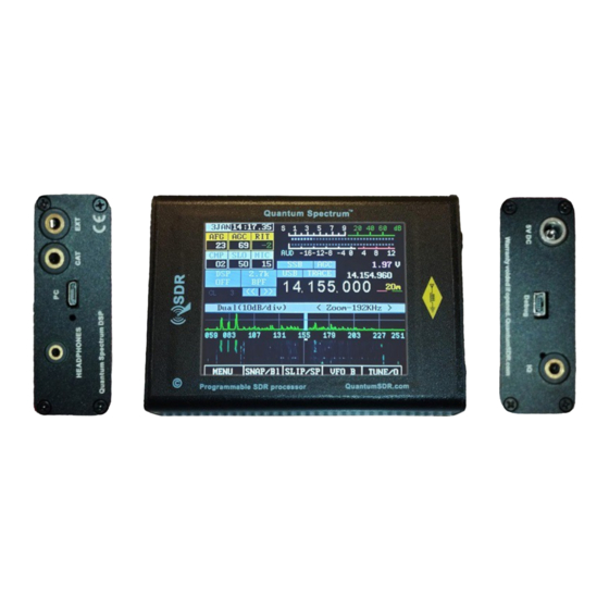
Page 21: A Brief Overview
A brief overview: Figure 7: Front panel of the Spectrum DSP NOTE: If you are unfamiliar with the Spectrum DSP, please refer to the section of the manual: “Before you get on the air - Initial set-up of the Spectrum DSP”... - Page 22 Initial SSB transmit audio set-up: (set-up dependent) Preferably, connect the Spectrum DSP to a 50 ohm dummy load capable of handling at • least 10 watts. Alternatively, you may tune to a clear frequency while connected to an antenna with a known-good 50 ohm match.
- Page 23 What to do if you notice that the ALC or AUDIO meters jump when you push PTT: In a quiet room with an antenna or dummy load connected to the Spectrum DSP, set the METER mode to ALC and key the microphone/transmitter without talking and note if ALC meter jumps at the instant that you key the transmitter and goes down again.
- Page 24 When the translate mode is activated and “magnify” mode is not turned on you will note that the receive signal is no longer in the center of the spectrum scope! Along the bottom of the spectrum scope you'll observe that the frequency display is changed, with the frequency in kHz being displayed in full under the graticule, being shifted left or right as noted above.
- Page 25 Using the Spectrum DSP with computer “Sound Card” (e.g. digital) modes via the Line-Input and Line-Output connections: The Spectrum DSP may be connected to a computer, tablet or smart phone via audio cables and the PTT line on the Microphone cable to allow modes such as SSTV, PSK31, WSPR or other digital “Sound Card”...
- Page 26 • turns white. Comments about the TUNE mode: When set to CW mode, when TUNE is activated the Spectrum DSP will produce a • carrier above the dial frequency by the amount of the setting of the “CW Side/Off Freq” (e.g. sidetone frequency).
- Page 27 Spectrum DSP M2 User Manual V1.1 Configuration of the Spectrum DSP for CW operation: Connect a key or paddle to jack J2 on the RF board: This is the connector next to the • DC power input. For connecting a paddle for Iambic keying: The TIP of the connector is DIT.
- Page 28 LCD to adjust the STG value. Press the paddle/key connected to the EXT port to cause the Spectrum DSP to enter •...
-
Page 29: Important Notes
Spectrum DSP M2 User Manual V1.1 The configuration menu system: The configuration menu may be entered by pressing the MENU button. When in the menu system, it may be navigated using the following touch strokes: Centre-right up/down swipes – Selects the individual menu item. - Page 30 Spectrum DSP M2 User Manual V1.1 The CONFIGURATION menu is hidden unless it is enabled by activating it by setting the last item in the main menu to ON. Note: All menu items are numbered, but the numbers are omitted here to simplify maintenance of this document as these numbers occasionally change as features are added/modified.
- Page 31 Spectrum DSP M2 User Manual V1.1 3.6k Filter. - This enables/disables the filter and when set to “Off”, this filter will be • eliminated from selection when filter button is pressed. The settings will be displayed in white if this filter is currently selected.
- Page 32 Spectrum DSP M2 User Manual V1.1 available: 1750 Hz and 2135 Hz. The tone burst is activated by pressing-and-holding button MENU while transmitting. FM RX Bandwidth – This selects the detection bandwidth when in FM mode: • Selection of “audio bandwidth” is disabled as it is irrelevant in FM mode and this setting is unlikely to be changed very often.
- Page 33 • requiring that the local oscillator be shifted up by the same amount. The received signals are tuned at the first graticule left of center on the spectrum scope. RX LO LOW - In this mode the signals are shifted above zero Hz by 6 kHz, •...
- Page 34 Spectrum DSP M2 User Manual V1.1 where a setting of 1 is unity. This is increased from unity to increase the amount of ALC action (compression). See the section about the adjustment of the ALC/Compressor. This setting will be displayed in RED and not adjustable unless “TX Audio Compress”...
- Page 35 Spectrum DSP M2 User Manual V1.1 calculate the actual transmit frequency. LSB – The receiver operates in LSB and the transmit frequency is below the • displayed frequency by the amount of the configured sidetone frequency (e.g. menu parameter “CW Side/Off Freq”). One must do some mental math to calculate the actual transmit frequency.
- Page 36 CW mode in many current-production Icom transceivers. Spectrum Scope related items: Spec. Scope 1/Speed - This selects the update rate of the spectrum scope, or it may • be set to OFF which disables the spectrum scope entirely. The OFF setting may be used to reduce the “helicopter”...
- Page 37 Spec/Wfall Ctr. Line – This is used to set the color of the vertical grid line that • coincides with the center frequency of the receiver on the spectrum display and waterfall display to make the “center tuning” frequency more obvious. When...
- Page 38 Scope NoSig Adj. - This adjust how low or high the “no signal” baseline will auto- • adjust on the spectrum scope. A low number will raise the baseline up while a high number will lower the baseline. Wfall NoSig Adj. - This adjust the background and overall brightness of the spectrum •...
-
Page 39: Configuration Menu
When the LCD backlight is turned off, the spectrum scope and waterfall are are also disabled (“frozen”, actually), reducing a potential noise source as well. Filter BW Display – This setting sets the colour of a line below the Spectrum Scope or • P 39... - Page 40 Spectrum DSP M2 User Manual V1.1 Waterfall display that graphically depicts both the bandwidth and frequency span of the currently selected filter and mode. Voltmeter Cal. - This setting is used to calibrate the on-screen voltmeter. A setting of •...
- Page 41 Spectrum DSP M2 User Manual V1.1 with care, considering the limits of the PLL, the surrounding hardware and the tuning algorithm itself: There are no guarantees that any of the hardware will work at all outside the “normal” tuning range!If you enable this feature and tune outside this range, note that the frequency will NOT be saved with a power-off.
- Page 42 Spectrum DSP M2 User Manual V1.1 The above offsets the display as follows: DSP related items: DSP NR BufLen – This is the length of the De-Correlation delay buffer. In order for the • DSP to tell a voice signal from noise, it must have a sample of each, but given the absence of a separate noise source, we have to “simulate”...
- Page 43 FFT Windowing – The use of “FFT Windowing” - the pre-processing of spectral data • before display – can greatly improve the visual performance of the Spectrum Scope and Waterfall display by decreasing “bin leakage” (e.g. “sidelobe”) - that is, the...
- Page 44 “leak” onto the display above and below the displayed frequency. The default setting is “Blackman” which is quite good in making the spectrum scope look sharper and preventing signals from “bleeding” into each other, but most of these...
- Page 45 Spectrum DSP M2 User Manual V1.1 offering a reasonable compromise between sidelobe rejection, width, and overall “look”. For more information than you ever wanted to know about FFT Windowing, see the article: http://en.wikipedia.org/wiki/Window_function [End of menu configuration items] P 45...
- Page 46 Spectrum DSP M2 User Manual V1.1 Notes about adjustment of DSP-related configuration values: DSP Noise Reduction parameters: The DSP Noise Reduction is active in either the DSP NR or NR+NOT mode and it performs noise reduction be detecting the coherent (e.g. non-random) properties of the human voice and quickly adapting a filter to pass those frequencies and blocking the other frequencies.
- Page 47 Spectrum DSP M2 User Manual V1.1 As the DSP “strength” setting is increased the rate of filter adaptation is slowed down. While this can have the effect of make a filter “stronger” to a degree by making it focus more...
- Page 48 “palettes” that range from simple grayscale to “cold-hot” to “rainbow” to represent weak to strong signals. ◦ There is also a “Magnify” or Zoom mode for both the Spectrum Scope and Waterfall Display mode that provides x32 magnification, reducing the visible spectral width from 192KHz to just +/- 3 kHz (6 kHz total).
- Page 49 With these connectors it is possible to interface with an external device (a computer or tablet/smart phone) and operate “Sound Card” modes with the Spectrum DSP such as SSTV, PSK31, WSPR and other analog/digital modes.
- Page 50 Spectrum DSP M2 User Manual V1.1 Operating voltage range: • ◦ 4 - 5.0 volts maximum ◦ As low as 3.5 volts, receive-only. Current consumption: • ◦ Receive: ◦ Approx. 140-160mA at 4.40 volts, minimum volume, maximum display brightness. ◦ The selection of minimum LCD display brightness can reduce this by 40-60mA.
- Page 51 The ALC (Automatic Level Control) (Set-up dependent) Prior to the addition of the ALC the POWER adjustment on the Spectrum DSP was somewhat irrelevant when in a voice mode as it only added effective attenuation in the audio path. If...
- Page 52 Spectrum DSP M2 User Manual V1.1 Speak normally if using the Microphone input, or set the nominal input level if you are • using the LINE Input mode. Use button F2 to select the AUDio meter. • Use button M1 (below ENC1, the left-hand encoder) to select the on screen CMP •...
- Page 53 Spectrum DSP M2 User Manual V1.1 as described below. SSB operation with minimal speech compression: Set the Microphone/Line gain as described in the previous section (e.g. around “0” on • the AUDio meter with occasional peaks to +6 to +10.) In the menu system, set the parameter ALC Release Time to the default setting of 10.
- Page 54 Spectrum DSP M2 User Manual V1.1 ALC Release Time: This sets the time, after audio has dropped below the current • threshold, that the ALC will take to release and reduce attenuation. When set to the default setting of 10, the ALC will have only a modest effect on the transmitted audio,...
- Page 55 Spectrum DSP M2 User Manual V1.1 10 kHz: Pre-detection bandwidth: +/-10kHz (20 kHz total); Post-detection bandwidth: • 10 kHz. 7.5 kHz: Pre-detection bandwidth: +/-7.5kHz (15 kHz total); Post-detection • bandwidth: 10 kHz. 6 kHz: Pre-detection bandwidth: +/-6kHz (12 kHz total); Post-detection bandwidth: •...
- Page 56 – mostly through additional low-frequency components (down below 100 Hz) and somewhat above 3000 Hz. While this can increase the audio fidelity on transmit, you should be aware that it can significantly shift the RF energy from the audio spectrum that contains speech intelligence and reduce the “talk power”.
- Page 57 – useful for checking for a simplex path. The “FM” produced by the Spectrum DSP is compatible with PM, which is to say that for modulation, a 6dB/octave pre-emphasis is applied and a 6dB/octave de-emphasis is done on receive audio: This is the worldwide standard for narrowband frequency modulation on amateur and commercial frequencies.
- Page 58 Spectrum DSP M2 User Manual V1.1 • 7.2 kHz – This is suitable only for “Narrow” operation and even this will result in a bit of added distortion as the filter about as narrow as it may be to pass audio. Using this setting the weak- signal sensitivity is the highest amongst the FM filter bandwidth settings since this narrowest filter also intercepts less noise under weak-signal conditions.
- Page 59 Spectrum DSP M2 User Manual V1.1 Additional comments: The audio (speech) processor is active on FM, but owing to the nature of FM communications • (e.g. low noise with good signals) “strong” compressor settings will likely result in audio that sounds vary “processed.”...
-
Page 60: Additional Settings
Additional settings: The following settings should be known to the Spectrum DSP operator. Please refer to the previous sections containing the menu items for more details on their use. Voltmeter Cal. - This calibrates the on-screen voltmeter: Only a known-accurate •... - Page 61 3. Tune in a strong, constant signal. This could be a shortwave broadcast station or a signal generator – a signal generator is preferred. 4. Tune the Spectrum DSP dial frequency 1 kHz above the carrier frequency to obtain a strong 1kHz audio note. Example: If your signal generator is set to 7200 kHz, you would tune to 7201 kHz.
- Page 62 3) Tune in a strong, constant signal. This could be a shortwave broadcast station or a signal generator – a signal generator is preferred. 4) Tune the Spectrum DSP dial frequency 1 kHz above the carrier frequency to obtain a strong 1 kHz audio note.
- Page 63 • requiring that the local oscillator be shifted up by the same amount. The received signals are tuned at the first graticule left of center on the spectrum scope and waterfall display when “magnify” mode is turned off. RX LO LOW - In this mode the signals are shifted ABOVE zero Hz by 12 kHz, •...
- Page 64 If the menu item “Spec/Waterfall magnify” is set to Off when the translate mode is activated, you will note that the receive signal is no longer in the center of the spectrum scope or waterfall display, it is shown at it's offset frequency. Along the bottom of the spectrum scope you'll observe that the frequency display is changed, with the frequency in kHz being displayed in full under the graticule, being shifted left or right as noted above.
-
Page 65: Menu Mode
Toggle Spectrum Scope and Waterfall modes Main operational (receive/transmit) mode: Enter MENU mode Save settings to memory Enter Snap mode Balance the spectrum display to RX (ant. disconnected) Enter Slip tune mode Split working mode Toggle VFO A/B Activate fast virtual dial tuning mode... - Page 66 • Circuit description of the Spectrum DSP: The Spectrum DSP consists of one main unit and several optional additions: The main unit contains the MCU (processor), memory, audio codec, various sensors and a separate LCD touch display unit.
- Page 67 2. Connect the preamplifier to your radio's IQ port or tap. Then connect the preamplifier output jack to the IQ port on the Spectrum. You can also connect an IQ signal directly to the Spectrum DSP providing it has around 30mW PP for weak stations. USDX & (tr)usdx do not require a preamplifier, but the Xiegu G90 for example, does.
-
Page 68: Supplemental Information
Spectrum DSP M2 User Manual V1.1 Supplemental information The Spectrum M2 DSP is the fruit of a project aimed at bringing affordable Digital Signal Processing and Spectrum displays to radio enthusiasts, allowing classical and modern radios to be updated to a full range of modern features.
Need help?
Do you have a question about the DSP M2 and is the answer not in the manual?
Questions and answers