Advertisement
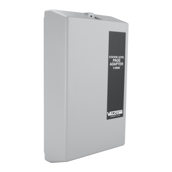
EXPANDABLE STATION LEVEL PAGE ADAPTER
INTRODUCTION
The V-9940 is an Expandable Station Level
Page Adapter designed to provide ring trip and
page access circuitry for use on standard device
telephone lines. These instructions contain the
specifications and information necessary to
install, operate and maintain the V-9940
Expandable Station Level Page Adapter.
I
: Please review dip switch
MPORTANT
settings (page 3) for equipment suitability.
FCC Information
When installing the V-9940, contact the local
Telephone Company and give them the
following information:
•
The telephone number of the line to which
the V-9940 will connect;
•
The FCC Registration #: BAF9I7-13957-
OT-N;
•
The ringer equivalence number: 1.1A
If the V-9940 is disconnected from its present
line, contact the local Telephone Company to
make them aware of the change.
Telephone Company Procedures: the goal of
the telephone company is to provide the best
service possible. In order to do this, it may
occasionally be necessary for them to make
changes in their equipment, operations or
procedures. If these changes potentially affect
the service or the operation of customer
equipment, the Telephone Company will give
written notice to allow any changes necessary to
maintain uninterrupted service.
SPECIFICATIONS
Access Methods
•
Centrex numbers
•
Loop start and ground start central office
lines
•
PABX station numbers
Figure 1 depicts a block diagram of a typical
PABX installation.
V-9940
Features
•
Ring trip on first ring
•
600 Ohms output; 8 Ohms output with AGC
•
Multiple units may be used for multi-zone
paging with all call behind a PABX
•
Use with Valcom multi-zone page control
unit for multi-zone paging Centrex or C. O.
lines (DTMF signaling only)
•
Use with Valcom handsfree page units for
talkback paging
•
Background music input
•
Open loop detect reset
•
Audio sensing circuit for reset
•
Time out reset
•
Manual reset
•
Answer verification tone
•
All call override tone
•
Battery reversal indicator
•
Auxiliary Make/Break contact
•
Built in 66 type connection block
•
Complies with UL 145
1
Issue 7
947740
Advertisement
Table of Contents

Summary of Contents for Valcom V-9940
-
Page 1: Fcc Information
PABX • Use with Valcom multi-zone page control unit for multi-zone paging Centrex or C. O. lines (DTMF signaling only) • Use with Valcom handsfree page units for talkback paging • Background music input • Open loop detect reset •... -
Page 2: Power Requirements
The V-9940 may be directly connected to Valcom One-Way Amplified speaker assemblies or may be used in conjunction with Valcom one zone or multi-zone page adapters. The following sections describe possible arrangements and detail the equipment required. -
Page 3: Dip Switch Settings
STATION LEVEL PAGING CAN NOT BE USED. Consult the Valcom catalog for an appropriate trunk level page adapter. If there is silence of at least 10 SECONDS before any tones are returned, then one-way paging may be used. If the line REMAINS SILENT for at least 1 and 1/2 minutes after disconnect, then one-way or talkback paging may be used. -
Page 4: Installation
General The following sections contain step-by-step instructions for wiring the V-9940 and associated Valcom equipment. If the results of a test do not correspond with what is shown, DO NOT PROCEED UNTIL THE PROBLEM HAS BEEN CORRECTED. During installation, Figure 2 may be referred to for location and numbering of punchdown block. -
Page 5: Power Connections
of the unit. Provisions for mounting to a single or double gang junction box are provided. See Figure 5. Open the V-9940 enclosure to allow access to connections and option switches. Slide the rear of the unit (contains the board) onto the mounting plate. - Page 6 FIGURE 5 MOUNTING EXPLODED VIEW...
-
Page 7: Wiring Instructions
Connect Tip of the PABX, Centrex or C. O. Line to pin 16 and Ring to Pin 17 of the V-9940. ____ 2. Connect Tip of the Valcom one-way amplified speaker assemblies being used to the V-9940 pin 8 and Ring to pin 9. - Page 8 WIRING INSTRUCTIONS Place a check by each step as it is completed. ___ 1a. Connect Tip of the PABX station number for zone one to pin 16 and Ring to pin 17 of the V-9940 being used for zone one. ___ 1b.
- Page 9 ____ 1. Connect Tip of the PABX Station, Centrex or C. O. Line to pin 16 of the V-9940. ____ 2. Connect Ring of the line to pin 17. ____ 3. Crossconnect pin 6 of the V-9940 to pin 1 of the V-9941A. ____ 4.
-
Page 10: Operation
____ 2. Connect Ring of the line to pin 17. ____ 3. Crossconnect pin 6 of the V-9940 to the Tip "WHITE/BLUE" of a Valcom multi-zone dial select page control unit (such as the V-1109RTVA or V-1109RTHF). ____ 4. Crossconnect pin 7 of the V-9940 to the control unit Ring "BLUE/WHITE". -
Page 11: Technical Assistance
GROUND Valcom, Inc. warrants its products to be free from defects in materials and workmanship under conditions of normal use and service for a period of one year from the date of shipment. The obligation under this warranty shall be limited to the replacement, repair or... - Page 12 This warranty is in lieu of and excludes all other warranties, expressed or implied and in no event shall Valcom, Inc. be liable for any anticipated profits, consequential damages, loss of time or other losses incurred by the buyer in connection with the purchase, operation or use of the product.


Need help?
Do you have a question about the V-9940 and is the answer not in the manual?
Questions and answers