
Related Manuals for Bauer Kompressoren Verticus 5


Summary of Contents for Bauer Kompressoren Verticus 5
- Page 1 Operating Manual and Spare Parts Catalog High Pressure Compressors for Breathing Air 225 bar 330 bar 420 bar Verticus 5 Copyright 2014 BAUER Kompressoren GmbH München...
- Page 3 DESCRIPTION INSTALLATION, TAKING INTO OPERATION OPERATION MAINTENANCE, REPAIR STORAGE, PRESERVATION DIAGRAMS, DRAWINGS SPARE PARTS CATALOGUE...
- Page 5 Instruction Manual w VERTICUS 5 Compressor Units INTRODUCTION This manual contains operating instructions and mainte nance schedules for the breathing air compressor units of the model range VERTICUS 5 Model: _________________________ Serial no.: _________________________ WARNING ! Pneumatic high pressure system ! The breathing air produced with the compressor units de...
- Page 6 Instruction Manual w VERTICUS 5 Compressor Units INTRODUCTION NOTICE Layout and use of instruction manuals Working with pneumatic high pressure systems cannot always be considered safe and one should possess a minimum knowledge of how to operate them. For this reason, please read this instruction manual before oper...
- Page 7 ........A-28 11.4. COMPRESSOR CONTROLLER B-CONTROL II (optional extra for all Verticus 5 compressor units) ...
-
Page 8: Table Of Contents
Instruction Manual w VERTICUS 5 Compressor Units TABLE OF CONTENTS INSTALLATION, OPERATION ............. . - Page 9 Instruction Manual w VERTICUS 5 Compressor Units TABLE OF CONTENTS FINAL SEPARATOR / FILTER SYSTEM ............
- Page 10 Instruction Manual w VERTICUS 5 Compressor Units TABLE OF CONTENTS STORAGE, PRESERVATION ..............
- Page 11 Instruction Manual w VERTICUS 5 Compressor Units TABLE OF FIGURES Fig. 1 Compressor unit, V series Super-Silent; front view, condensate collector fitted .....
- Page 12 Instruction Manual w VERTICUS 5 Compressor Units TABLE OF FIGURES Fig. 57 Control settings ............... .
- Page 13 Instruction Manual w VERTICUS 5 Compressor Units TABLE OF FIGURES Fig. 113 Pressure maintaining/non-return valve 350 bar ..........
- Page 14 Instruction Manual w VERTICUS 5 Compressor Units INDEX Intake air quality, C-11 Ambient temperature, A-18, A-66, B-6 Intake filter, A-16, D-5 Automatic condensate drain, A-21, D-14 Intermediate separators, A-16, D-6 Changing the oil type, A-16, D-4 Compressor control unit, B-Control II, A-47...
- Page 15 Instruction Manual w VERTICUS 5 Compressor Units INDEX Repair instructions, D-18 Residual CO contents, A-71 Residual CO2 contents, A-71 Residual oil vapour contents, A-71 Residual water contents, A-71 Safety valves, A-19, D-13 Final pressure, D-13 Operating check, D-13 Sales, xii...
- Page 16 Instruction Manual w VERTICUS 5 Compressor Units Change notice Change no. Change date and changes Basic edition April 2000 May 2002 January 2003, new compressor block June 2003, new compressor block January 2004, new compressor block June 2004, new compressor block...
- Page 17 Instruction Manual w VERTICUS 5 Compressor Units...
- Page 18 Instruction Manual w VERTICUS 5 Compressor Units...
- Page 19 1.1. PURPOSE AND SHORT DESCRIPTION Frame and housing assembly with instrument panel This instruction manual describes the breathing air com pressor units of the VERTICUS 5 model range: Filter set V 12.14 Automatic condensate drain V 150 ...
-
Page 20: Fig. 1 Compressor Unit, V Series Super-Silent; Front View, Condensate Collector Fitted
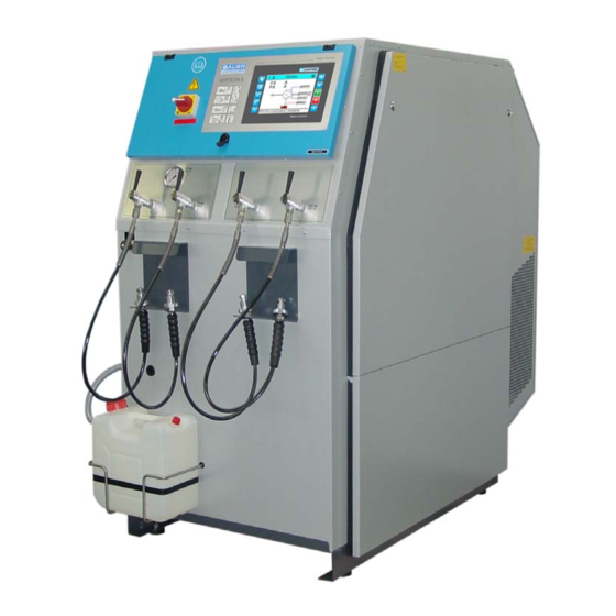
Instruction Manual w VERTICUS 5 Compressor Units Fig. 1 Compressor unit, V series Super-Silent; front view, condensate collector fitted 1 Main switch 2 Filling valve 300 bar 3 Scavenging valve 4 Condensate collector, 10 ltrs. 5 Compressor control unit 6 Filling panel 300 bar... -
Page 21: Fig. 2 Compressor Unit, V Series Open; Rear View
Instruction Manual w VERTICUS 5 Compressor Units Fig. 2 Compressor unit, V series open; rear view 1 Automatic condensate drain unit 2 Condensate separator 3 Mains connection 4 Intake filter 5 Compressor block 6 Filter system 7 Venting valve with pressure gauge... -
Page 22: Fig. 3 Compressor Unit, V Series Super-Silent; Front View, With Top Mounted B-Kool And Cooling Air Duct
Instruction Manual w VERTICUS 5 Compressor Units Fig. 3 Compressor unit, V series Super-Silent; front view, with top mounted B-KOOL and cooling air duct 1 Main switch 2 Filling pressure gauge 3 Scavenging valve 4 Condensate collector, 10 ltrs. 5 B-KOOL... -
Page 23: Fig. 4 Filling Panel With 2 Pressure Ranges And Switch-Over Valve
BAUER filling panels are available as an optional extra for permanently available by means of a pressure reducer. all Verticus 5 breathing air compressors. According to re On filling panels with a pressure reducer, bottles can be quirements, they can be equipped with filling valves for filled simultaneously at different pressures, whereas on ... -
Page 24: Fig. 5 External Filling Panel, Design For Open Housing 300 Bar With B-Control Control Unit
Instruction Manual w VERTICUS 5 Compressor Units 1 Filling valve 300 bar 4 ON-OFF button 2 Filling pressure gauge 300 bar 5 Failure warning light 3 Emergency OFF button 6 B-CONTROL control unit Fig. 5 External filling panel, design for open housing 300 bar with B-CONTROL Control unit... -
Page 25: Fig. 6 External Filling Panel; 6X 300 Bar, 4X 200 Bar With B-Control Control Unit
Instruction Manual w VERTICUS 5 Compressor Units Filling panels for 2 pressure ranges The pressure reducer is installed directly upstream of the lower pressure range. It reduces the filling pressure to the The filling panel is equipped with filling valves for both 200 desired pressure. -
Page 26: Fig. 7 Compressor Block Ik12.14
Instruction Manual w VERTICUS 5 Compressor Units Compressor blocks also roller bearings. This allows for an even longer life which lasts at least 30,000 operating hours. General Compressor block IK12.14 The compressor block IK12.14 is used to compress air in The compressor blocks are particularly suitable for continu... -
Page 27: Fig. 8 Compressor Block Ik150, Front View
Instruction Manual w VERTICUS 5 Compressor Units Compressor blocks IK150,IK180 IK15.1, IK15.11 and application, for industrial application up to 500 bar (7,000 IK18.1 psi). The max. allowable operating pressure (adjustment of final pressure safety valve) is 435 bar (6,300 psi) for breath... -
Page 28: Fig. 9 Compressor Blocks Ik15.1, Ik15.11, Front View
Instruction Manual w VERTICUS 5 Compressor Units Fig. 9 Compressor blocks IK15.1, IK15.11, front view 1 Service indicator 12 Inter-cooler 1st stage 2 Intake filter 13 Cylinder, 4th stage 3 Crankcase vent feedback line 14 After-cooler 4th stage 4 Cylinder, 1st stage... -
Page 29: Fig. 10 Compressor Block Ik180, Front View
Instruction Manual w VERTICUS 5 Compressor Units Fig. 10 Compressor block IK180, front view 1 Service indicator 12 Inter-cooler 1st stage 2 Intake filter 13 Cylinder, 4th stage 3 Crankcase vent feedback line 14 After-cooler 4th stage 4 Cylinder, 1st stage... -
Page 30: Fig. 11 Compressor Block Ik18.1, Front View
Instruction Manual w VERTICUS 5 Compressor Units Fig. 11 Compressor block IK18.1, front view 1 Service indicator 13 Inter-cooler 1st stage 2 Intake filter 14 After-cooler 5th stage 3 Oil separator, crankcase vent feedback line 15 Cylinder, 5th stage 4 Cylinder, 1st stage... -
Page 31: Fig. 12 Lube Oil Circuit, Ik12.14
Instruction Manual w VERTICUS 5 Compressor Units LUBRICATION SYSTEM This oil pump will operate in the correct sense of rotation, only. Otherwise, no oil pressure will be built up resulting in dam age of the compressor block. 2.1. FUNCTIONAL DESCRIPTION The oil pump (1, Fig. -
Page 32: Fig. 14 Intake Filter, Ik12.14
Instruction Manual w VERTICUS 5 Compressor Units The current oil list is provided in section F. Order this list regularly through the BAUER Technical Service Department. For operation under difficult conditions such as continuous running and/or high ambient temperatures we recommend the use of BAUER high performance compressor oils, only, according to the oil list. -
Page 33: Fig. 16 Filter System With Securus Monitoring
Instruction Manual w VERTICUS 5 Compressor Units 4.1. FUNCTIONAL DESCRIPTION is not replaced after indication of the preliminary warning message, the B-CONTROL compressor control will auto Intermediate separators are mounted after 2nd and 3rd matically shut down the compressor as soon as the cart... -
Page 34: Fig. 17 Pressure Maintaining/Non-Return Valve, 350 Bar
Instruction Manual w VERTICUS 5 Compressor Units cess by measuring the cartridge saturation within the filter PRESSURE MAINTAINING / NON- cartridge. RETURN VALVE 5.3. OIL AND WATER SEPARATOR 6.1. COMPRESSOR UNITS UP TO 350 BAR 5.3.1. Description A pressure maintaining and a non-return valve are provided downstream of the filter system. -
Page 35: Fig. 19 Final Pressure Gauge
B-CONTROL display. See chapter 11. Pressure gauges in the instrument panel are optional ex tras for all Verticus 5 units. If provided, the gauges should indicate the correct pressures during operation. 8.1. -
Page 36: Fig. 21 Valve Head 1St Stage
Instruction Manual w VERTICUS 5 Compressor Units Top view, IK12.14 intake side pressure side Top view, IK150 , IK180 , IK18.1 intake pressure pressure Top view, IK15.1 , IK15.11 pressure side intake side Fig. 21 Valve head 1st stage A-20... -
Page 37: Operation
Instruction Manual w VERTICUS 5 Compressor Units A condensate separator/silencer. AUTOMATIC CONDENSATE DRAIN A condensate tank. A bracket for mounting the drain unit on the com 10.1. COMPRESSOR BLOCKS IK12.14, IK150, pressor block or on the unit. -
Page 38: 10.2.1. Operation
Instruction Manual w VERTICUS 5 Compressor Units Three pneumatically operated condensate drain valves, pressure is relieved from the servo-pistons (8) of the con densate drain valves (5), (6) and (7) and the pistons are one each for the intermediate separators after 2nd and raised from the valve seats (9) by the 2nd stage pressure. -
Page 39: Fig. 26 Normal Operation
Instruction Manual w VERTICUS 5 Compressor Units signal. The required control medium applied to the solenoid Also every 15 minutes, but independently from solenoid valve is taken from the intermediate separator after the valve (4), 3/2-way solenoid valve (5) is energized for approx. -
Page 40: Fig. 28 Automatic Condensate Drain Unit Ik18.1
Instruction Manual w VERTICUS 5 Compressor Units A bracket for mounting the drain unit on the com pressor block or on the unit. Three electrical timers (part of the compressor control or built in a separate housing for units without com... -
Page 41: Fig. 31 Condensate Drain
CONDENSATE COLLECTOR 10 ltrs. 2nd stage pressure. The condensate from the intermediate BAUER Verticus 5 units are equipped as standard with a 10 separators after 2nd, 3rd and 4th stage is drained. After 6 liter condensate collector which can be mounted at the seconds, the solenoid valves are de-energized, and the sys... -
Page 42: Fig. 32 Condensate Collector, 40 Ltrs
Instruction Manual w VERTICUS 5 Compressor Units ally switched off by a max. level contact, or an alarm system Contact function can be changed by mounting the switch provided by the customer can be activated. The separated coil upside down. - Page 43 Instruction Manual w VERTICUS 5 Compressor Units Technical data Tank capacity: approx. 60 litres Condensate capacity: approx. 40 litres Activated charcoal contents: 3,700 g Connecting hose length: 1,150 mm Dimensions: approx. 410 mm x 330 mm x 1,000 mm (W x D x H) 10.8.
-
Page 44: 11.3.1. General
Instruction Manual w VERTICUS 5 Compressor Units ELECTRICAL SYSTEM or compressor stop value is exceeded (one pressure or both pressure values, depending on the configuration) the compressor switches off. If the pressure falls below 11.1. GENERAL the switch-on pressure or the compressor start value... - Page 45 Instruction Manual w VERTICUS 5 Compressor Units Do not make any changes to the programmes operator or customer service technician. This instruction manual describes the settable parameters, but it cannot (software). go deeper into the specific settings for these diverse ...
-
Page 46: Fig. 36 Operating And Display Elements
Instruction Manual w VERTICUS 5 Compressor Units Control and monitoring elements The operating panel consists of an LCD colour display and 6 function keys for controlling all functions on the compressor installation. See Fig. 36. Selection of the func tion boxes is by using the cursor buttons. - Page 47 Instruction Manual w VERTICUS 5 Compressor Units Menu and navigation The LCD display contains important information concer ning the combination installation. Start page Fig. 37. This page is displayed after booting the control sys tem. The page continues to be displayed as long as no menu operation has been carried out.
- Page 48 Instruction Manual w VERTICUS 5 Compressor Units Measured values (Page 1) Measured values Page 1 shows: Oper.hours. Operating hours Start cycles 0 cycles Start cycles Final pressure 1 Final pressure 1 Final pressure 2 Final pressure 2 Intake pressure Display of the analogue measured values is by bar graph with additional digital display.
- Page 49 Instruction Manual w VERTICUS 5 Compressor Units Measured values (Page 4) Page 4 shows: Temp. stage 1 Temperature stage 1 Temp. stage 2 Temperature stage 2 Temperature stage 3 Temp. stage 3 Temperature stage 4 Temp. stage 4 The measured values are displayed as per Page 1, with a bar graph.
- Page 50 Instruction Manual w VERTICUS 5 Compressor Units Compressor Setup Set values The "Final pressure" box is always shown. The boxes intake Final pressure > pressure or gas balloon level only if the individual sensors are registered. Intake pressure > Gas balloon level >...
- Page 51 Instruction Manual w VERTICUS 5 Compressor Units Gas balloon level (optional) Gas balloon level You must take account of the fact that the compressor stop value is under the compressor start value. The compressor Gas balloon level thus stops if the level of the gas balloon falls below the...
- Page 52 Instruction Manual w VERTICUS 5 Compressor Units Operating mode (dropdown operating mode) Operating mode The selection window for the operating type appears as a dropdown in the actual operating type window. Combined operation Semi-automatic Mode of operation Operating mode (Example 2)
- Page 53 Instruction Manual w VERTICUS 5 Compressor Units Control logic Control logic On the Control logic screen the regulating parameters are stipulated for controlling the compressor or combination Start control installation. Control 1 Final pressure 1 Control 1, control 2: selection between final pressure 1, Logic->...
- Page 54 Instruction Manual w VERTICUS 5 Compressor Units Valve test Valve test Here we show on the one hand, the current condition of the condensate valves/intake valve (open/closed) non- regis Cond.valve 1 closed tered valves are not shown. For valve testing you can select the individually desired Cond.valve 2...
- Page 55 Instruction Manual w VERTICUS 5 Compressor Units SECURUS SECURUS Entitlement to editing from level "SERVICE" Configuration The SECURUS and SECCANT CAN screens provide the logged off operating data of each individual unit. These screens are configured in the factory and normally do not need to be Delivery modified.
- Page 56 Instruction Manual w VERTICUS 5 Compressor Units B-Control Setup B-Control Setup Time/Date Display Alarm relay Software Language/Units Time/Date Time/Date Display and setting the current time and date. Release Edit from level "Operation" Set time and date The operating hours counter can only be seen and edited only from level "Admin".
- Page 57 Instruction Manual w VERTICUS 5 Compressor Units Software Software Header: Plant No., Software version Entitlements: Save configuration > Save configuration, Load configuration, Load configuration > Update software since level "SERVICE". Update software > Load factory settings from level "OPERATION". Load factory settings...
- Page 58 Instruction Manual w VERTICUS 5 Compressor Units Load factory settings Load factory settings This setting restores the original BAUER settings that were present when the plant was delivered. Actual configuration is loaded from The current saved configuration SD card. All current settings are overridden!
- Page 59 Instruction Manual w VERTICUS 5 Compressor Units Message relay Alarm relay For the alarm relay three different operating modes can be configured. Standard mode "only errors" is that only error can allow the relay to drop out (Fail Safe). Alarm relay signals: In the mode "Errors and warnings flashing"...
- Page 60 Instruction Manual w VERTICUS 5 Compressor Units Maintenance Maintenance The Maintenance screen stipulates the maintenance intervals and show the momentary values of the Maintenance intervals compressor. The box for Diagnosis is only displayed if the operator is logged in as an Administrator.
- Page 61 Instruction Manual w VERTICUS 5 Compressor Units Log-in (registration) Service log-in There are 4 registration levels: OPERATION SERVICE CONFIG ADMIN The higher level has, in each case also the entitlement for the lower levels. Log-in (registered) Service log-in When a user is registered an open key symbol appears in...
- Page 62 Instruction Manual w VERTICUS 5 Compressor Units Current message list Messages (empty) No active warnings/errors There are no active warnings/errors. Right at the bottom of the page there is a button to open logbook or the message history. Logbook Acknowledge...
-
Page 63: Fig. 38 B-Control Control Panel And Display
Instruction Manual w VERTICUS 5 Compressor Units 11.4. COMPRESSOR CONTROLLER B-CONTROL II (optional extra for all Verticus 5 com pressor units) The electric control is placed in the control room at the right side of the compressor building. The unit is only allowed to operate... -
Page 64: Fig. 39 Operating And Display Elements
Instruction Manual w VERTICUS 5 Compressor Units 11.4.2. HARDWARE AND CONNECTIONS For reference to the hardware and connections refer to the schematic diagrams in section F. For more detailed information about the control system, refer to the circuit diagramme that comes with the unit. -
Page 65: Fig. 40 Cf Card Removal
Instruction Manual w VERTICUS 5 Compressor Units 11.4.4. Storage media and connections CompactFlash memory card The configuration file for the control system is stored on a CompactFlash card. This file is created automatically at the factory during commissioning and does not need to be modified. -
Page 66: Fig. 42 Home Page
Instruction Manual w VERTICUS 5 Compressor Units 11.4.5. Menu and navigation Home page When switching on the compressor unit, or by pressing the F5 key, the home page (Fig. 42) is displayed, giving the most important general data in a clear graphical presentation. - Page 67 Instruction Manual w VERTICUS 5 Compressor Units A click on the header causes the serial number of the com pressor together with the software version being displayed as shown in Fig. 45. The installation can be named by using the middle box and with the appropriate authorisation.
-
Page 68: Fig. 47 Actual Values
Instruction Manual w VERTICUS 5 Compressor Units 11.4.6. Actual values The actual values page shows the current operating data for the compressor, i.e. monitored values, as shown in Fig. 47. ****** indicates that this sensor is not being used. Press the arrows in the footer to display further values. -
Page 69: Fig. 50 Trend Page
Instruction Manual w VERTICUS 5 Compressor Units 11.4.7. Trend The Trend page shows a graphical representation of the pressure process and the on and off times of the com pressor in the bottom half. Depending on the software ver sion, different diagrams can be selected or the F9 and F10 keys (see Fig. -
Page 70: Fig. 52 Log-In Page
Instruction Manual w VERTICUS 5 Compressor Units 11.4.9. Log in On the Log in page (Fig. 52) the operator or the mainte nance staff can access higher levels which require access authorisation to make any modification. In order to enter a specific level, enter the password and confirm with the enter key (tick, Fig. -
Page 71: Fig. 55 Operation Menu
Instruction Manual w VERTICUS 5 Compressor Units 11.4.10. Parameterization parametrization combined compressors installation should be carried out by an experienced operator or a BAUER service technician only. Operation The Operation menu (Fig. 55) contains several sub-menus for the setting of the following parameters:... -
Page 72: Fig. 58 Pressure Values
Instruction Manual w VERTICUS 5 Compressor Units Control settings The regulation settings to control the unit are defined on the Control settings page (Fig. 57). Control point 1, control point 2: selection between final pressure 1, final pressure 2, suction pressure, gas balloon analogue, gas balloon digital. -
Page 73: Fig. 59 Combined Operation
Instruction Manual w VERTICUS 5 Compressor Units Combined operation The combi page (Fig. 59) defines the status of the compressor in a combined installation. The controller can be declared as master or as slave. A master compressor controls the whole combined installation; a slave compressor is controlled by the master. -
Page 74: Fig. 61 Service Menue
Instruction Manual w VERTICUS 5 Compressor Units 11.4.11. SERVICE MENUE The Service menue consists of the submenues: Maintenance Lubrication Separator Diagnosis and Alarm relay Logbook export Fig. 61 Service menue Maintenance The Maintenance page shows maintenance intervals and actual (elapsed) values. -
Page 75: Fig. 64 Diagnosis Page
Instruction Manual w VERTICUS 5 Compressor Units Diagnosis page The diagnosis page (Fig. 49) shows values of the various si gnal channels. That are raw values wich are of interest for the customer service only. Fig. 64 Diagnosis page Pre-lubrication page For certain compressor models a pre-lubrication after pro... -
Page 76: Fig. 69 Sensors
Instruction Manual w VERTICUS 5 Compressor Units 11.4.12. Setup The Setup page (Fig. 67) enabless the setting of various parameters: Language: German, English, Russian, etc. Pressure unit: bar, Mpa, psi, psig If you still use psi or psig please note that Mpa is the only pressure unit having international validity. -
Page 77: Fig. 70 Valves
Instruction Manual w VERTICUS 5 Compressor Units Valves The Valves pages enables the setting of condensat drain valves and intake shut-off valve (if provided). The operating mode (Normally Close or Normally Open) of the valve is selected with the help of the list field. -
Page 78: Fig. 74 Bus Communication
Instruction Manual w VERTICUS 5 Compressor Units The B-VPN page allows the setting of B-Messenger 2. B-VPN Enter all necessary information about the unit in the text fields contained in the different pages: description of the unit with type, location, operator etc. (Fig. 73). Press the arrows in the footer to scroll the pages. -
Page 79: Fig. 78 Hex Switch, Operating Mode Position
Instruction Manual w VERTICUS 5 Compressor Units Display Setup Contrast and brightness of the display are set on the Display Setup page (Fig. 76). Fig. 76 Display Setup Touch calibration If the touch display is not working properly recalibration may produce relief. -
Page 80: Fig. 79 System Setup
Instruction Manual w VERTICUS 5 Compressor Units Setup System The System Setup page enables to enter the network data for the connection with a computer. Select a type of connection in the „serial online“ field: INA: standard connection protocol ... -
Page 81: Fig. 82 Securus Page
Instruction Manual w VERTICUS 5 Compressor Units SECURUS and SECCANT The Securus and Seccant pages show the operating data of the corresponding device (if provided). These page are configured at the factory and normally, do not required mo dification. In case of update with one or both devices, the configuration should be carried out in the configuration le... -
Page 82: Fig. 84 Cooling Air Flow
Instruction Manual w VERTICUS 5 Compressor Units COMPRESSOR DRIVE SYSTEM COOLING SYSTEM The cylinders of the compressor block, the intermediate As standard, the compressor is driven by the drive motor coolers and the after-cooler are air-cooled. For this pur through V-belts. Direction of rotation is left, looking at the pose, the compressor is equipped with a fanwheel which cooling fan, i.e. - Page 83 Instruction Manual w VERTICUS 5 Compressor Units 13.1. TECHNICAL DATA To minimize multiple quotations, the common features are listed under Gen eral, all compressor block and motor data are listed in 13.1.2. and 13.1.3., respec tively. 13.1.1. Compressor Units General: Medium .
- Page 84 Instruction Manual w VERTICUS 5 Compressor Units Compressor unit ... V 15.1-7.5 . . . V 15.1-11 ..V 15.11-11 V 18.1-11 ..V 18.1-15 Compressor block .
- Page 85 Instruction Manual w VERTICUS 5 Compressor Units TECHNICAL DATA (Cont.) Compressor block ....... . .
- Page 86 Instruction Manual w VERTICUS 5 Compressor Units TECHNICAL DATA (Cont.) Compressor block ....... . .
- Page 87 Instruction Manual w VERTICUS 5 Compressor Units TECHNICAL DATA (Cont.) 13.1.4. Filter systems a. General Service pressure, standard 225/330/420 bar (3,200/4,500/6,000 psi) Service pressure, max. 420 bar (6,000 psi) Flow rate P61: max. 600 l/min P81: max. 1,000 l/min Regenerated volume of air, referenced to 1 bar abs, 20C, P61: 2,200 m ;...
- Page 88 Instruction Manual w VERTICUS 5 Compressor Units NOTES A-72...
- Page 89 Instruction Manual w VERTICUS 5 Compressor Units...
- Page 90 Instruction Manual w VERTICUS 5 Compressor Units...
-
Page 91: Fig. 85 Room Temperature
Locating the unit 1.3. COOLING AIR DUCT INSTALLATION On all Verticus 5 units the cooling air outlet can be installed as standard in two different ways. By simply removing the air outlet cover and grid and mounting them in the desired position, the air outlet can either be on top or on the back Fig. -
Page 92: Fig. 87 Installation (Natural Ventilation
Instruction Manual w VERTICUS 5 Compressor Units For further information on the installa A Minimum distance from wall, intake side: tion of air cooled compressors, see our In Standard unit: 0.5 m stallation Manual which can be obtained Super-Silent unit: 0 m from BAUER Customer Services, P.O. -
Page 93: Fig. 88 Installation With Natural Ventilation, Example
Instruction Manual w VERTICUS 5 Compressor Units Fig. 88 to Fig. 90 show installation examples with natural ventilation: Correct: Air intake low, cooling air flows Incorrect: Air intake high, cooling air does not though unit reach unit Fig. 88 Installation with natural ventilation, example 1... -
Page 94: Fig. 91 Installation (Artificial Ventilation
Instruction Manual w VERTICUS 5 Compressor Units 1.6. ARTIFICIAL VENTILATION Free air flow effected by a blower ventilation by means of an air channel with or without For drive powers above 11 kW natural ventilation may not additional blower be sufficient. Under certain circumstances this can also ap... -
Page 95: Fig. 92 Installation With Artificial Ventilation, Example
Instruction Manual w VERTICUS 5 Compressor Units Correct: Air flows along an imaginary Incorrect: Cooling air does not re streamline through the compressor ach unit Fig. 92 Installation with artificial ventilation, example 1 Correct: cooling air led directly to unit... -
Page 96: Fig. 94 B-Controlr-Control Unit
Instruction Manual w VERTICUS 5 Compressor Units 3-phase, 2,2 kW (direct starting) 3-phase, 3 kW (star-delta starting) 3-phase, 3 kW (direct starting) 3-phase, 4 kW (star-delta starting) 3-phase, 4 kW (direct starting) 3-phase, 5,5 kW (star-delta starting) 3-phase, 5,5 kW (direct starting) - Page 97 Instruction Manual w VERTICUS 5 Compressor Units CONNECTING STORAGE BOTTLES ally using the flywheel to ensure that all parts are turning free. Check that all fastening bolts and threaded pipes (OPTIONAL) are secure and sealed, if necessary tighten them to the Compressor units with factory installed storage bottle(s) on correct torque value.
- Page 98 Instruction Manual w VERTICUS 5 Compressor Units B-10...
- Page 99 Instruction Manual w VERTICUS 5 Compressor Units...
- Page 100 Instruction Manual w VERTICUS 5 Compressor Units...
- Page 101 Instruction Manual w VERTICUS 5 Compressor Units OPERATION 1.2. IDENTIFYING THE SAFETY NOTICES Important instructions concerning the endangerment of SAFETY MEASURES personnel, technical safety and operating safety will be spe cially emphasized by placing the following signs before the 1.1.
- Page 102 Instruction Manual w VERTICUS 5 Compressor Units In addition to the instruction manual, provide supple 1.3.3. Qualifications, fundamental duties mentary instructions for supervision and monitoring du Work on / with the machine / unit may only be carried ties taking into consideration exceptional factors e.g.
- Page 103 Instruction Manual w VERTICUS 5 Compressor Units Before carrying out any exceptional work or repairwork, If it is necessary to remove safety devices for mainten operating personnel should be informed. Call the super ance and repairwork, these must be replaced and visor.
- Page 104 Instruction Manual w VERTICUS 5 Compressor Units Soundproofing equipment on the machine / unit must Vessels for static load: be in place and functional during operation. These pressure vessels are permanently under virtually The stipulated hearing protectors must be worn.
- Page 105 Instruction Manual w VERTICUS 5 Compressor Units Be particularly careful with second-hand pressure ves for obtaining permission. In addition, the documents be sels, when their previous operating mode is not specific longing to the unit are important for recurrent inspections ally clarified.
- Page 106 Instruction Manual w VERTICUS 5 Compressor Units OPERATION 2.2. STARTING THE UNIT (B-CONTROL) Knocking, audible when starting, is due 2.1. PREPARATION FOR OPERATION to the last stage floating piston. This knocking disappears as soon as there is The compressors described in this pressure between the stages, and the pis...
-
Page 107: Fig. 96 Control Panel, B-Control
Instruction Manual w VERTICUS 5 Compressor Units 2.2.2. B-CONTROL II (Touch panel) BEHAVIOUR IN THE CASE OF FAILURE In order to start the compressor unit, the customer provided Resetting fault message main switch must be on. A warning, fault or maintenance message is reset resp. - Page 108 Instruction Manual w VERTICUS 5 Compressor Units The compressor unit have to be protected against automatical restart, when the service switch is activated or the power supply to the motor is interrupted. Place a warning sign on the service switch!
-
Page 109: Fig. 97 Scavenging Valve
Instruction Manual w VERTICUS 5 Compressor Units 2.5. FILLING PROCEDURE . The technically caused excessive increase of CO dur ing the filling process and the CO peak at taking the unit into operation. Because of the reasons stated above 2.5.1. -
Page 110: Fig. 98 International Filling Connector
Instruction Manual w VERTICUS 5 Compressor Units 2.5.5. Filling the bottles Set filling valve handle to filling position (1, Fig. 100). Open bottle valve (2) - bottle will be filled. Drain con densate regularly during filling. On units with automatic condensate drain check that condensate is drained reg... - Page 111 Instruction Manual w VERTICUS 5 Compressor Units...
- Page 112 Instruction Manual w VERTICUS 5 Compressor Units...
-
Page 113: Maintenance Record
Instruction Manual w VERTICUS 5 Compressor Units MAINTENANCE, REPAIR The used cartridge must be disposed of according to local regulations. GENERAL 1.1. MAINTENANCE RECORD Maintenace of drive motor/engine ac We recommend that all maintenance work is recorded in cording to manufacturer's operating in... -
Page 114: Oil Change Intervals
Instruction Manual w VERTICUS 5 Compressor Units Remove from filler neck Fig. 104/Fig. 105). Drain oil while still warm by means of oil drain plug. On units equipped with oil drain hose remove hose union nut from coupling at hose bracket. Collect oil in a suit... -
Page 115: Intake Filter
Instruction Manual w VERTICUS 5 Compressor Units wrong phase sequence - venting of the oil pump may be ne cessary. Proceed as follows: With the compressor running and all condensate drain valves open to avoid pressure being built up during this procedure, unscrew screw cap and plug (3, Fig. -
Page 116: Intermediate Separators
Instruction Manual w VERTICUS 5 Compressor Units Mount new filter element. Mount cover . 3.1.2. IK150, IK15.1, IK15.11, , IK180, IK18.1 The underpressure in the intake filter is monitored by ser vice indicator (4, Fig. 109). As soon as the max. allowable underpressure is reached, indication will change from green to red. -
Page 117: Final Separator / Filter System
Instruction Manual w VERTICUS 5 Compressor Units FINAL SEPARATOR / FILTER SYSTEM 5.1.2. Condensate drain The condensate produced by the re-cooling after the com 5.1. OIL AND WATER SEPARATOR pression process has to be drained regularly by means of the manual condensate drain valves ... -
Page 118: Fig. 111 Removing The Filter Head
Instruction Manual w VERTICUS 5 Compressor Units Unscrew the filter head (1, Fig. 111) with the special 5.2.3. Filter replacement intervals spanner (2) supplied with the unit. The number of operating hours or the amount of possible bottle fillings per filter cartridge can be determined by the tables of pages D-9 to D-12 taking into consideration the ambient temperature and the cartridge used. - Page 119 Instruction Manual w VERTICUS 5 Compressor Units 1. Filter system P61; Filter cartridge 058826: Filter cartridge lifetime [hours] Filling pressure p = 200 bar DeliveryQ [l/min] Ambient Temperature temperature of final separ tU [C] ator tAb [C] 20 - 24...
- Page 120 Instruction Manual w VERTICUS 5 Compressor Units 2. Filter system P61; Filter cartridge 058827: Filter cartridge lifetime [hours] Filling pressure p = 200 bar DeliveryQ [l/min] Ambient Temperature temperature of final separ tU [C] ator tAb [C] 20 - 24...
- Page 121 Instruction Manual w VERTICUS 5 Compressor Units 3. Filter system P81; Filter cartridges 058825 + 058826: Filter cartridge lifetime [hours] Filling pressure p = 200 bar DeliveryQ [l/min] Ambient Temperature temperature of final separ tU [C] ator tAb [C] 20 - 24...
- Page 122 Instruction Manual w VERTICUS 5 Compressor Units 4. Filter system P81; Filter cartridges 058825 + 058827: Filter cartridge lifetime [hours] Filling pressure p = 200 bar DeliveryQ [l/min] Ambient Temperature temperature of final separ tU [C] ator tAb [C] 20 - 24...
-
Page 123: Pressure Maintaining / Non-Return Valve
Instruction Manual w VERTICUS 5 Compressor Units PRESSURE MAINTAINING / NON- 7.1.1. 225 bar and 330 bar compressor units RETURN VALVE The safety valve is mounted on top of the final separator. Turn knurled knob on top of the valve clockwise until valve blows off (Fig. -
Page 124: Pressure Gauges
Instruction Manual w VERTICUS 5 Compressor Units PRESSURE GAUGES AUTOMATIC CONDENSATE DRAIN We recommend that pressure gauges are checked from 10.1. GENERAL time to time. For this purpose we have developed a special test pressure gauge with an adaptor which immediately re... -
Page 125: Float Switch Maintenance
Instruction Manual w VERTICUS 5 Compressor Units 11.4. B-CONTROL BATTERY REPLACEMENT Item Part no. Qty. rq'd Activated charcoal 3700 g General points Fleece 72207 Replace the buffer battery as soon as the fault message "Replace buffer battery" appears. 10.5. FLOAT SWITCH MAINTENANCE Battery replacement must only be carried out by qualified personnel. -
Page 126: Compressor Drive System
Instruction Manual w VERTICUS 5 Compressor Units Replace if necessary. If more than one V-belt is installed, always replace the complete set. MAINTENANCE ON FILLING VALVES Maintenance work on the filling panels includes merely cleaning and changing the filling valves as well as checking the safety valves. -
Page 127: Filling Valves On External Filling Panel
Instruction Manual w VERTICUS 5 Compressor Units To do so, unscrew T connection on the filling valve. Remove 13.2.3. Replacing damaged components sintered metal filter with a screwdriver and clean filter in Certain components, such as piston and gaskets, can be... -
Page 128: Inspections
Instruction Manual w VERTICUS 5 Compressor Units 14.2. INSPECTIONS The storage bottles have to be maintained at regular inter vals. This results in inner inspections every 5 years, pressure tests every 10 years and outer inspections every 2 years, which have to be performed by the local authorities. -
Page 129: Trouble-Shooting
Instruction Manual w VERTICUS 5 Compressor Units TROUBLE-SHOOTING Trouble Cause Remedy Drive Motor (electric) Motor will not start Electric circuitry faulty Before attempting to make any re pairs, check all fuses, terminal connec tions, wire leads, make sure that mo... - Page 130 Instruction Manual w VERTICUS 5 Compressor Units Trouble Cause Remedy Electric Control System Control does not switch on No control voltage Check feed line Control fuse defective Replace fuse, eliminate cause Control current line cut off, line or Tighten terminal...
- Page 131 Instruction Manual w VERTICUS 5 Compressor Units Alarm messages B-Control Micro English [en] Final pressure 1 sensor faulty Final pressure 2 sensor faulty Intake pressure sensor faulty Oil press. sensor faulty or direction of rotation incorrect Interm. press. sensor 1 faulty Interm.
- Page 132 Instruction Manual w VERTICUS 5 Compressor Units English [en] Temperature cooling air too high Temperature last stage too low Temperature last stage too high Temperature stage 1 too high Temperature stage 2 too high Temperature stage 3 too high Temperature stage 4 too high Temperature gas discharge too high Temp.sensor Spare Ch.18 min.
- Page 133 Instruction Manual w VERTICUS 5 Compressor Units English [en] SECURUS+ temperature measurement error SECURUS offline Spare Spare Maintenance due Spare Spare Spare Spare Spare Factory default memory inconsistent Processy data memory inconsistent Parameter memory inconsistent > factory settings have been loaded! No configuration found! >...
- Page 134 Instruction Manual w VERTICUS 5 Compressor Units B-Control Micro trouble shooting Fault message Cause Remedy Final pressure sensor 1 faulty Line faulty or short circuit Check the line as per the circuit diagram. Sensor faulty Replace the sensor. Final pressure sensor 2 faulty...
- Page 135 Instruction Manual w VERTICUS 5 Compressor Units Fault message Cause Remedy Temperature sensor stage 1 Line faulty or short circuit Check the line as per the circuit faulty diagram. Sensor faulty Replace the sensor. Temperature sensor stage 2 Line faulty or short circuit...
- Page 136 Instruction Manual w VERTICUS 5 Compressor Units Fault message Cause Remedy Intake pressure too high Gas supply pressure too high Adjust the gas supply. See the operating instructions for the compressor. Oil pressure too low Oil level too low Refill oil. See the operating instructions for the compressor.
- Page 137 Instruction Manual w VERTICUS 5 Compressor Units Fault message Cause Remedy Temperature cooling air too Room ventilation is inadequate Improve the ventilation of the high compressor room. See the operating instructions for the compressor. Last stage temp. too low Compressor too cold Check and/or increase the room temperature.
- Page 138 Instruction Manual w VERTICUS 5 Compressor Units Fault message Cause Remedy Spare Ch.22 max. Spare Ch.23 min. Spare Ch.23 max. Oil level too low Not enough oil Refill oil. See the operating instructions for the compressor. Motor protection/automatic Too many consumers at the same time Check the complete installation.
- Page 139 Instruction Manual w VERTICUS 5 Compressor Units Fault message Cause Remedy Spare Spare Spare Emergency off pressed Emergency off pressed Check the Emergency off and reset it. SECURUS+ temperature measurement error SECURUS offline ____ Spare Spare Maintenance due Target times reached Carry out the compressor maintenance activities.
- Page 140 Instruction Manual w VERTICUS 5 Compressor Units B-CONTROL II ALARM LIST English [en] [PLC_Alarms].ID[38:0] final pressure 1 sensor faulty [PLC_Alarms].ID[39:1] final pressure 2 sensor faulty [PLC_Alarms].ID[40:2] inlet pressure sensor faulty [PLC_Alarms].ID[41:3] oil pressure sensor faulty, or rotation wrong [PLC_Alarms].ID[42:4] intermediate pressure sensor 1st stage faulty [PLC_Alarms].ID[43:5]...
- Page 141 Instruction Manual w VERTICUS 5 Compressor Units English [en] [PLC_Alarms].ID[77:39] dewpoint high / filterlifetime max [PLC_Alarms].ID[78:40] level gasballoon low [PLC_Alarms].ID[79:41] level gasballoon high [PLC_Alarms].ID[80:42] cooling air temperature low PLC_Alarms].ID[81:43] cooling air temperature high PLC_Alarms].ID[82:44] temperatur last stage low PLC_Alarms].ID[83:45] temperatur last stage high PLC_Alarms].ID[84:46]...
- Page 142 Instruction Manual w VERTICUS 5 Compressor Units English [en] PLC_Alarms].ID[117:79] Combi slave 3 faulty PLC_Alarms].ID[118:80] Combi slave 4 faulty PLC_Alarms].ID[119:81] PLC_Alarms].ID[120:82] gaswarndevice faulty PLC_Alarms].ID[121:83] gaswarning > 20% PLC_Alarms].ID[122:84] gasalarm > 40% PLC_Alarms].ID[123:85] ATEX emergency off TRIP PLC_Alarms].ID[124:86] emergency off TRIP PLC_Alarms].ID[125:87]...
- Page 143 Instruction Manual w VERTICUS 5 Compressor Units B-CONTROL II TROUBLESHOOTING Fault message Cause Remedy Final pressure sensor Broken wire or short circuit Check wiring acc. to schem. diagram defective Sensor defective Replace sensor Final pressure sensor Broken wire or short circuit Check wiring acc.
- Page 144 Instruction Manual w VERTICUS 5 Compressor Units Fault message Cause Remedy Spare sensor Ch. 19 defective Broken wire or short circuit Check wiring acc. to schem. diagram Sensor defective Replace sensor Spare sensor Ch. 20 defective Broken wire or short circuit Check wiring acc.
- Page 145 Instruction Manual w VERTICUS 5 Compressor Units Fault message Cause Remedy Crankcase pressure min. Gas supply to crankcase low Gas supply to crankcase prüfen bzw. jus tieren. Refer to compressor operation manual Crankcase pressure max. Gas supply to crankcase high Check gas supply to crankcase and adjust setting.
- Page 146 Instruction Manual w VERTICUS 5 Compressor Units Fault message Cause Remedy Cooling water temperature Fan of heat exchanger defective Check fan max. Sense of rotation des Lüfters falsch Check sense of rotation. Fan should blow upwards Heat exchanger dirty Clean heat exchanger...
- Page 147 Instruction Manual w VERTICUS 5 Compressor Units Fault message Cause Remedy Motor protection Fan overload Check fan for free movement. triggered Check wiring. Reset circuit breaker Wrong setting Adjust circuit breaker according to schematic diagram. Circuit breaker defective Check circuit...
- Page 148 Instruction Manual w VERTICUS 5 Compressor Units Fault message Cause Remedy Fault input 3 triggered Compressor 1 blocked, manual Compressor too long out of operation Lubricate compressor Refer lubricating required compressor operation manual Compressor 2 blocked, manual Compressor too long out of operation...
-
Page 149: Tables
Instruction Manual w VERTICUS 5 Compressor Units TABLES 17.1. TIGHTENING TORQUE VALUES Unless otherwise specified in text, the fol lowing torque values apply. All valve head screws require torque wrench tight ening! The indicated torque values are valid for bolts in greased condition. Re... -
Page 150: Lubrication Chart
Instruction Manual w VERTICUS 5 Compressor Units 17.3. LUBRICATION CHART Usage Lubricants Rubber and plastic parts, filter housing threads WEICON WP 300 WHITE part no. N19752 BAUER special lubricant P/N 072500 Sealing rings BAUER special lubricant P/N 072500 Shaft seal (seal) - Page 151 Instruction Manual w VERTICUS 5 Compressor Units...
- Page 152 Instruction Manual w VERTICUS 5 Compressor Units...
-
Page 153: Storage, Preservation
Instruction Manual w VERTICUS 5 Compressor Units STORAGE, PRESERVATION GENERAL PRESERVING THE MOTOR/ENGINE If the compressor is put out of service for more than six Preserve the motor/engine according to the instructions of months, the unit should be preserved in accordance with the motor/engine manufacturer. -
Page 154: Transportation
Instruction Manual w VERTICUS 5 Compressor Units Check the oil pressure on the pressure gauge or the oil flow in the sight glass. If there is any fault, check the lu brication of the compressor. After 10 minutes, close the filling valves or the outlet valve and run the unit up to final pressure until the final pressure safety valve blows. - Page 155 Instruction Manual w VERTICUS 5 Compressor Units...
- Page 156 Instruction Manual w VERTICUS 5 Compressor Units...
-
Page 157: Diagrams, Drawings
Compressor unit Verticus 5, breathing air units V series in the Super-Silent housing with filling 129963-13 panel - direct filling valves Compressor unit Verticus 5, breathing air units V series in the open housing with filling panel - di 129963-15 rect filling valves... - Page 158 Instruction Manual w VERTICUS 5 Compressor Units...
- Page 159 Instruction Manual w VERTICUS 5 Compressor Units Connection data for three-phase motors Operating voltage 230 V Operating voltage 400 V/500 V Mains cable Mains cable Nomi Nomi Fuse values for Fuse values for Drive Drive wire gauge in wire gauge in...
- Page 160 Instruction Manual w VERTICUS 5 Compressor Units...
- Page 161 Instruction Manual w VERTICUS 5 Compressor Units...
- Page 162 Instruction Manual w VERTICUS 5 Compressor Units...
-
Page 163: Parts Lists
Instruction Manual w VERTICUS 5 Compressor Units PARTS LISTS COMPRESSOR UNITS 1.1. COMPRESSOR UNIT V 12.14 Applicable spare parts lists: Code Verticus 5 compressor units Compressor block Filter system Automatic condensate drain unit Instrument panel Frame and panelling Drive system... -
Page 164: Compressor Unit
Instruction Manual w VERTICUS 5 Compressor Units 1.3. COMPRESSOR UNIT V 180 Applicable spare parts lists: Code Verticus 5 compressor units Compressor block Filter system Automatic condensate drain unit K150, K180 Instrument panel Frame and panelling Drive system Accessories Filling panels... - Page 165 Instruction Manual w VERTICUS 5 Compressor Units 1.5. COMPRESSOR UNIT V 15.11 Applicable spare parts lists: Code Verticus 5 compressor units Compressor block Filter system Automatic condensate drain unit K150, K180 Instrument panel Frame and panelling Drive system Accessories Filling panels...
- Page 166 Instruction Manual w VERTICUS 5 Compressor Units 1.7. COMPRESSOR UNIT V 12.14 Super-Silent Applicable spare parts lists: Code Verticus 5 compressor units Compressor block Filter system Automatic condensate drain unit Instrument panel Frame and panelling Drive system Accessories Filling panels...
- Page 167 Instruction Manual w VERTICUS 5 Compressor Units 1.9. COMPRESSOR UNIT V 180 Super-Silent Applicable spare parts lists: Code Verticus 5 compressor units Compressor block Filter system Automatic condensate drain unit K150, K180 Instrument panel Frame and panelling Drive system Accessories...
- Page 168 Instruction Manual w VERTICUS 5 Compressor Units 1.11. COMPRESSOR UNIT V 15.11 Super-Silent Applicable spare parts lists: Code Verticus 5 compressor units Compressor block Filter system Automatic condensate drain unit K150, K180 Instrument panel Frame and panelling Drive system Accessories...
Need help?
Do you have a question about the Verticus 5 and is the answer not in the manual?
Questions and answers
Our compressor not reched final pressure .keep shutdown at 50bar
The Bauer Kompressoren Verticus 5 compressor may shut down at 50 bar and not reach the final pressure if the intake pressure or gas balloon level falls below the configured compressor stop value. The compressor only restarts when the intake pressure or gas balloon level rises above the compressor start value. The final pressure is also dependent on system settings and sensor registration. If sensor 2 is not registered, Final Pressure 2 will not be displayed or used.
This answer is automatically generated