Sign In
Upload
Manuals
Brands
Bauer Kompressoren Manuals
Air Compressor
Verticus 5
Bauer Kompressoren Verticus 5 Manuals
Manuals and User Guides for Bauer Kompressoren Verticus 5. We have
1
Bauer Kompressoren Verticus 5 manual available for free PDF download: Operating Manual And Spare Parts List
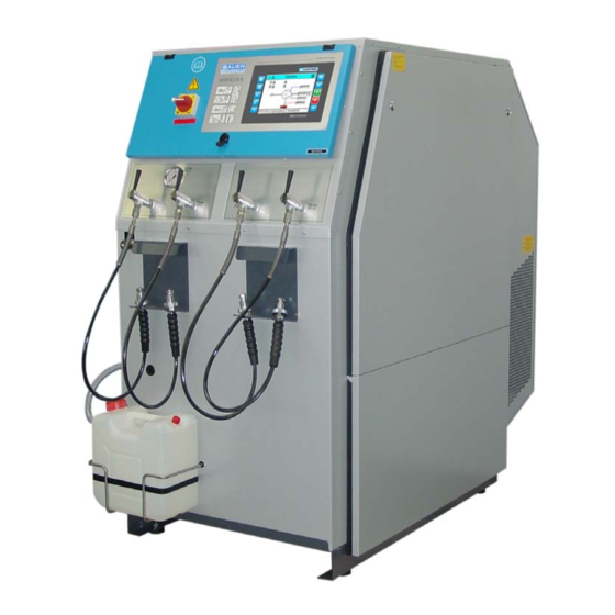
Bauer Kompressoren Verticus 5 Operating Manual And Spare Parts List (168 pages)
High Pressure Compressors for Breathing Air 225/330/420 bar
Brand:
Bauer Kompressoren
| Category:
Air Compressor
| Size: 2 MB
Table of Contents
Table of Contents
8
Fig. 1 Compressor Unit, V Series Super-Silent; Front View, Condensate Collector Fitted
20
Fig. 2 Compressor Unit, V Series Open; Rear View
21
Fig. 3 Compressor Unit, V Series Super-Silent; Front View, with Top Mounted B-KOOL and Cooling Air Duct
22
Fig. 4 Filling Panel with 2 Pressure Ranges and Switch-Over Valve
23
Fig. 5 External Filling Panel, Design for Open Housing 300 Bar with B-CONTROL Control Unit
24
Fig. 6 External Filling Panel; 6X 300 Bar, 4X 200 Bar with B-CONTROL Control Unit
25
Fig. 7 Compressor Block IK12.14
26
Fig. 8 Compressor Block IK150, Front View
27
Fig. 9 Compressor Blocks IK15.1, IK15.11, Front View
28
Fig. 10 Compressor Block IK180, Front View
29
Fig. 11 Compressor Block IK18.1, Front View
30
Fig. 12 Lube Oil Circuit, IK12.14
31
Fig. 13 Lube Oil System IK150 to IK18.1
31
Fig. 14 Intake Filter, IK12.14
32
Fig. 15 Intake Filter, IK150, IK180, IK18.1
32
Fig. 16 Filter System with SECURUS Monitoring
33
Fig. 17 Pressure Maintaining/Non-Return Valve, 350 Bar
34
Fig. 18 Pressure Maintaining/Non-Return Valve, 420 Bar
34
Fig. 19 Final Pressure Gauge
35
Fig. 20 Valve Operation
35
Fig. 21 Valve Head 1St Stage
36
Operation
37
Fig. 22 Automatic Condensate Drain Unit
37
Fig. 23 Normal Operation
37
10.2.1. Operation
38
Fig. 24 Condensate Drain
38
Fig. 25 Automatic Condensate Drain Unit IK15.11
38
Fig. 26 Normal Operation
39
Fig. 27 Condensate Drain
39
Fig. 28 Automatic Condensate Drain Unit IK18.1
40
Fig. 29 Drain Valve 2Nd Stage, IK18.1
40
Fig. 31 Condensate Drain
41
Fig. 32 Condensate Collector, 40 Ltrs
42
Fig. 33 Float Switch Orientation
42
Fig. 34 Condensate Collector, Function
42
11.3.1. General
44
Fig. 35 B-Control Micro
44
Fig. 36 Operating and Display Elements
46
Fig. 38 B-Control Control Panel and Display
63
Fig. 39 Operating and Display Elements
64
Fig. 40 CF Card Removal
65
Fig. 41 Connections
65
Fig. 42 Home Page
66
Fig. 44 Alarm List, Not Confirmed
66
Fig. 47 Actual Values
68
Fig. 48 Actual Values
68
Fig. 49 Actual Values
68
Fig. 50 Trend Page
69
Fig. 51 Logbook Page
69
Fig. 52 Log-In Page
70
Fig. 53 Keyboard
70
Fig. 54 Log-In Page, Configuration Level
70
Fig. 55 Operation Menu
71
Fig. 58 Pressure Values
72
Fig. 59 Combined Operation
73
Fig. 61 Service Menue
74
Fig. 62 Maintenance Page
74
Fig. 63 Logbook Export Page
74
Fig. 64 Diagnosis Page
75
Fig. 65 Pre-Lubrication Page
75
Fig. 69 Sensors
76
Fig. 70 Valves
77
Fig. 71 B-Messenger
77
Fig. 72 Message Filter
77
Fig. 74 Bus Communication
78
Fig. 75 Backup
78
Fig. 78 Hex Switch, Operating Mode Position
79
Fig. 79 System Setup
80
Fig. 80 Set Time
80
Fig. 81 Logger Page
80
Fig. 82 Securus Page
81
Fig. 83 Seccant Page
81
Fig. 84 Cooling Air Flow
82
Fig. 85 Room Temperature
91
Fig. 86 Locating the Unit
91
Fig. 87 Installation (Natural Ventilation
92
Fig. 88 Installation with Natural Ventilation, Example
93
Fig. 89 Installation with Natural Ventilation, Example
93
Fig. 90 Installation with Natural Ventilation, Example
93
Fig. 91 Installation (Artificial Ventilation
94
Fig. 92 Installation with Artificial Ventilation, Example
95
Fig. 93 Installation with Artificial Ventilation, Example
95
Fig. 94 B-Controlr-Control Unit
96
Fig. 96 Control Panel, B-Control
107
Fig. 97 Scavenging Valve
109
Fig. 98 International Filling Connector
110
Fig. 99 Connecting Air Bottle
110
Fig. 100 Filling Air Bottle
110
Fig. 101 Removing Air Bottle
110
Maintenance Record
113
Maintenance Work
113
Maintenance Intervals
113
Lubrication System
113
Oil Level Check
113
Oil Change Intervals
114
Oil Capacity
114
Oil Packages
114
Oil Change
114
Changing the Oil Type
114
Venting Oil Pump
114
Fig. 102 Oil Sight Gauge IK12.14
114
Fig. 103 Oil Sight Gauge IK150, IK15.1, IK15.11, IK180, IK18.1
114
Intake Filter
115
Maintenance
115
Fig. 104 Oil Filler, IK12.14
115
Fig. 105 Oil Filler, IK150, IK15.1, IK15.11, IK180, IK18.1
115
Fig. 106 Removing the Cover
115
Fig. 107 Replacing the Oil Filter
115
Intermediate Separators
116
Maintenance
116
Fig. 108 Intake Filter, IK12.14
116
Final Separator / Filter System
117
Oil and Water Separator
117
Purifier
117
Fig. 110 Oil and Water Separator, 420 Bar
117
Fig. 111 Removing the Filter Head
118
Fig. 112 Extracting the Cartridge
118
Pressure Maintaining / Non-Return Valve
123
Maintenance
123
Safety Valves
123
Operating Check
123
Blow-Off Pressure Check
123
Fig. 114 Final Pressure Safety Valve, 225 and 330 Bar
123
Fig. 115 Final Pressure Safety Valve, 420 Bar
123
Pressure Gauges
124
Valves
124
Changing the Valves
124
Valve Change
124
Automatic Condensate Drain
124
Maintenance
124
Activated Charcoal Maintenance
124
Float Switch Maintenance
125
Electrical System
125
Drive Motor
125
Electric Control
125
Pressure Switch
125
B-Control Battery Replacement
125
Fig. 116 Final Pressure Switch
125
Fig. 117 Removing Cover
125
Compressor Drive System
126
Electric Drive Motor
126
V-Belts
126
Maintenance on Filling Valves
126
Filling Valves on V5 Filling Panel
126
Fig. 118 Taking out the Battery
126
Fig. 119 Battery Handling
126
Fig. 120 Filling Valve 075353
126
Filling Valves on External Filling Panel
127
Maintenance of Storage Bottles
127
Lifetime
127
Fig. 121 Filling Valve
127
Inspections
128
Condensate Drain
128
Repair Instructions
128
Trouble-Shooting
129
Tables
149
Tightening Torque Values
149
Torque Sequence
149
Fig. 122 Torque Sequence
149
Lubrication Chart
150
Adhesive and Sealant Chart
150
Testing Agents
150
Storage, Preservation
153
General
153
Preparation
153
Preserving the Compressor
153
Preserving the Motor/Engine
153
Preventive Maintenance During Storage
153
Changing the Lube Oil for Preserving
153
Reactivating the Compressor Unit
153
Transportation
154
Diagrams, Drawings
157
Flow Diagrams
157
Drawings
157
Lists
157
Schematic Diagrams
157
Parts Lists
163
Compressor Units
163
Compressor Unit
163
Compressor Unit
164
Advertisement
Advertisement
Related Products
Bauer Kompressoren JUNIOR II
Bauer Kompressoren Profi-Line CAPITANO 140-B
Bauer Kompressoren Profi-Line CAPITANO 140-E
Bauer Kompressoren Profi-Line MARINER 200-B
Bauer Kompressoren Profi-Line MARINER 200-E
Bauer Kompressoren Profi-Line MARINER 250-B
Bauer Kompressoren Profi-Line MARINER 250-E
Bauer Kompressoren Profi-Line MARINER 320-B
Bauer Kompressoren Profi-Line MARINER 320-E
Bauer Kompressoren Categories
Air Compressor
Industrial Equipment
Dryer
More Bauer Kompressoren Manuals
Login
Sign In
OR
Sign in with Facebook
Sign in with Google
Upload manual
Upload from disk
Upload from URL