
Related Manuals for edc RD400P


Summary of Contents for edc RD400P
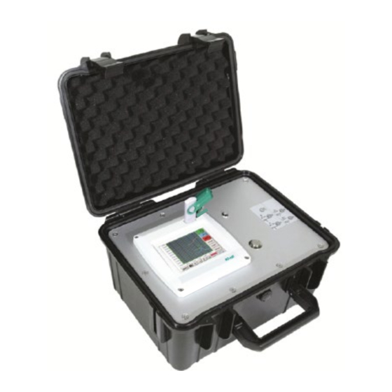
- Page 1 EN English Installation and operating instructions intelligent paperless recorder RD400P RD400P Rev1.0 Jul20 Page 1 of 108...
-
Page 2: Foreword
I. Foreword Dear customer, thank you very much for deciding in favour of the RD400P. Please read this installation and operation manual carefully before mounting and initiating the device and follow our advice. A riskless operation and a correct functioning of the RD400P... -
Page 3: Table Of Contents
Three- and four-wire power supply 0 - 1/10/30 VDC ............16 7.2.7 Two-, three- and four-wire connector pin assignments for PT100/PT1000/KTY81 ..17 Connection with RS485 ....................... 17 Connect the RD400P with a PC ...................18 RD400P Rev1.0 Jul20 Page 3 of 108... - Page 4 Table of contents Operation RD400P .......................19 Switching on / off of the RD400P ..................19 Main menu (Home) ....................... 19 9.2.1 Initialization ........................19 9.2.2 Main menu after initialization ................... 20 Settings ..........................21 9.3.1 Password-Settings ......................21 9.3.2 Sensor-Settings ....................... 22 9.3.2.1...
- Page 5 Table of contents 9.3.4 Set backlight ........................66 9.3.5 Cleaning ........................... 67 9.3.6 System-Status........................67 9.3.7 About RD400P ......................... 67 9.3.8 Virtual Channels (optional) ....................68 9.3.8.1 Option „Virtual Channels“ activation ................. 68 9.3.8.2 Virtual Channels Einstellung..................69 9.3.8.3 Selection of Sensor-type ..................69 9.3.8.4...
-
Page 6: Safety Instructions
This instruction manual must be available at any time at the operation site of the RD400P. Regional and national regulations respectively, have to be observed in addition to this instruction manual if necessary. -
Page 7: Installation
Batteries no longer suitable for use can be directly returned at: CS Instruments GmbH Zindelsteiner Str. 15 D-78052 VS-Tannheim CS Instruments GmbH Am Oxer 28c D-24955 Harrislee RD400P Rev1.0 Jul20 Page 7 of 108... -
Page 8: Application Area
From recording of the measured data, automatic sensor identification, indication on a big colour screen, alerting, storage up to remote read-out via web server, all that is possible with RD400P. By means of the EDC-Soft, software alarms can be sent via SMS or e-mail. -
Page 9: Intended Use
Intended use Intended use The RD400P data logger serves for the stationary measured data acquisition and storage of analogue and digital input signals. The RD400P data logger is exclusively designed and constructed for the proper application purpose that is described herein and must only be used correspondingly. -
Page 10: Technical Data Rd400P
Technical data RD400P Technical data RD400P Dimensions of housing 270x225x156 mm Weight 2.2 kg Case Material impact resistant HDPE/HWU –plastic (ABS). (2x2) sensor inputs for analogue and digital sensors freely allocable. Digital sensors for dew point and consumption with SDI interface PR/DT400 Series. -
Page 11: Input Signal
± 0,3 °C ( further range ) minimal pulse length 100 μs Pulse frequency 0 - 1 kHz Measuring range max. 30 VDC Cable cross-section Sensor circuit points/Output signal ODU Medi-Snap, AWG26 cable cross-sections: 0,14 mm RD400P Rev1.0 Jul20 Page 11 of 108... -
Page 12: Connection Diagrams Of The Different Sensor Types
View on welding pins of Medi Snap Connector Cable lenght 5 / 10 m weiss white braun brown grün green gelb yellow grau grey rosa pink blau blue Depending on the connected boards (digital or analogue) are the inputs useable. RD400P Rev1.0 Jul20 Page 12 of 108... -
Page 13: Connection Diagrams
Sensor PR 415 Pulse Input Grün/Green The digital data transmission between RD400P and the dew point sensors PR 415 and PR 300 occur via the SDI bus line. + RS485 (A) - RS485 (B) It´s possible to connect the PR 300/PR 425 alternatively as 4 – 20 mA... -
Page 14: Connection Pulse Sensors
-Vb Gnd R = 4K7 Loop Loop (+) I Attention: PT Gnd The RD400P is counting a Grau/Grey (-) V - PT - I consumption unit, by switching „power on“. (+) V- PT Gelb / Yellow PT Supply... -
Page 15: Analogue Two-, Three-, And Four-Wire Current Signal
-Vb Gnd Loop Loop ß +4 … 20mA RD400P (+) I Gelb / Yellow PT Gnd à +4 … 20mA (-) V - PT - I Grau/Grey (+) V- PT PT Supply Analogboard RD400P Rev1.0 Jul20 Page 15 of 108... -
Page 16: Three- And Four-Wire Power Supply 0 - 1/10/30 Vdc
Sensor Rot/Red -Vb Gnd Loop Loop Sensor with voltage output in 4-wire technology (+) I PT Gnd Grau/Grey (-) V - PT - I Gelb / Yellow (+) V- PT PT Supply Analogboard RD400P Rev1.0 Jul20 Page 16 of 108... -
Page 17: Two-, Three- And Four-Wire Connector Pin Assignments For Pt100/Pt1000/Kty81
(+) V- PT Yellow PT Supply Rosa / Pink Analogboard Connection with RS485 +24Vdc -Vb Gnd Loop Loop Sensor Pulse Input Sensor with RS485 Interface + RS485 (A) RS 485 - RS485 (B) Digitalboard RD400P Rev1.0 Jul20 Page 17 of 108... -
Page 18: Connect The Rd400P With A Pc
9.3.3.3 Network-Settings Reboot the RD400P: See chapter,9.3.3.6.6 Factory-Reset The RD400P can be connected with the PC by a crossover cable, which has a RJ45 plug on each side, or an Ethernet cable with a crossover adapter. Crossover-Cable with RJ45-plug Crossover-Adapter After connecting the RD400P via a suitable cable to the PC, you can make graphical and tabular data evaluations with the EDC Basic software. -
Page 19: Operation Rd400P
Switching on / off of the RD400P To switch on / off the RD400P you have to press ( >= 3sec) the on / off knob. A short press of the on / off knob during operation opens a popup with indication of the remaining operation time. -
Page 20: Main Menu After Initialization
Before the first sensor setting is made, the language and time should be set! Remark: Language Chapter 9.3.3.1 Main Settings Device Settings Set Language Chapter 9.3.3.2 Date & Time Main Settings Device Settings Date & Time RD400P Rev1.0 Jul20 Page 20 of 108... -
Page 21: Settings
New password in red font. repeat If you can’t remember the password, please use Master password in order to enter a new password. Remark: The master password is supplied together with the instrument’s documentation. RD400P Rev1.0 Jul20 Page 21 of 108... -
Page 22: Sensor-Settings
Depending on the version 2 or 4 channels. Remark: Usually no channels preset! Back Remark: Depending on selected variant following combinations are possible: combination Channel D = Digital-Channel A = Analog-Channel RD400P Rev1.0 Jul20 Page 22 of 108... -
Page 23: Choice Of The Sensor Type (For Example Type Digital Sensor)
(see next step). Main menu Settings Sensor settings A1 Type description field Digital Now the is selected for the Type Digital DT/PR 400 series and confirmed by pressing button. RD400P Rev1.0 Jul20 Page 23 of 108... -
Page 24: Name The Measurement Data And Define The Decimal Places
2345678 0.00 Attention: Before the selected measurement data are recorded, the data logger must be activated after the settings(See chapter 9.3.11 Logger settings (data logger)). RD400P Rev1.0 Jul20 Page 24 of 108... -
Page 25: Alarm-Settings
Main menu Settings Sensor settings A1 Alarm-Button Relay-buttons It is possible to select from 5 different delays. T0 is preset to no delay. The delays (T1 to T4) are free definable but are common valid for all relays. RD400P Rev1.0 Jul20 Page 25 of 108... - Page 26 Main menu Settings Sensor settings A1 Name After the alarm activation at channel A1. 0,00 ltr/min 2345678 0,00 Cancel Remark: After confirm with OK, the font is black again and the values and settings are accepted. RD400P Rev1.0 Jul20 Page 26 of 108...
-
Page 27: More Settings (Scale Analogue Output)
Digital available! More-Settings 110.00 0.000 200.000 The settings finished by pushing the button! Remark: After confirming with OK, the font is black again and the values and settings are accepted. RD400P Rev1.0 Jul20 Page 27 of 108... -
Page 28: Dew Point Sensor Pr400/Pr410 Of Type Digital (Sdi Bus)
Now the Type Digital is selected for the DT(VA)/PR(FA) 5xx series and confirmed by pressing the button. The RD400P detects, if the connected sensor is a flow or dew point sensor of PR(FA)5xx 7,26 °Ctd /DT(VA)5xx and set the Digital subtype automatically correct. -
Page 29: Flow Sensor Dt400/Dt410 Of Type Digital (Sdi Bus)
Type Digital DT(VA)/PR(FA) 400 series and confirmed by pressing the button. Cancel The RD400P detects, if the connected sensor 7,26 °Ctd is a flow or dew point sensor with SDI interface and set the Digital subtype automatically correct. - Page 30 There is no uniform standard for the tube inner diameter! (Please, inquire at the manufacturer or measure by your own !) RD400P Rev1.0 Jul20 Page 30 of 108...
- Page 31 20 °C, 1000 hPa (according to ISO 1217 intake condition) 0 °C and 1013 hPa (= standard cubic meter) can also be entered as a reference. Do not enter the operation pressure or the operation temperature under reference conditions! RD400P Rev1.0 Jul20 Page 31 of 108...
-
Page 32: Dew Point Sensor Pr500/Pr510 Of Type Pr5Xx (Rs 485 Modbus)
°C characters. 5.6314 g/m³ Confirmation by pressing the OK-button. Type Name Dew Point The connection with the PR(FA)5xx sensor is done after confirmation by pressing “OK”. 3.33 °Ctd 23.313 25.85 °C 5.6314 g/m³ RD400P Rev1.0 Jul20 Page 32 of 108... -
Page 33: Settings Dew Point Sensor Pr500/Pr510
The value is entered in the corresponding text field. The unit can be freely selected, selection menu is opened by pressing the corresponding button units Confirm the settings by pressing the button. RD400P Rev1.0 Jul20 Page 33 of 108... -
Page 34: Definition Of Reference Pressure (Absolute Pressure Value)
Main menu Settings Sensor settings A1 arrow right (2.page)Pressure Setting Textfield Ref.Pressure Reference pressure is the pressure for that the dew point in relaxation will be back-calculated. Default- Value is 1013 mbar (Atm. Pressure). Confirm the settings by pressing the button. RD400P Rev1.0 Jul20 Page 34 of 108... -
Page 35: Calibration
• • Sensor error / System error 4..20 Output according Namur ( 3.8mA – 20.5 mA) • < 4mA to 3.8 mA Measuring range under range >20mA to 20.5 mA Measuring range exceeding RD400P Rev1.0 Jul20 Page 35 of 108... -
Page 36: Flow Sensor Of Type Dt5Xx (Rs 485 Modbus)
It is possible to enter a name with max. 24 characters. Confirmation by pressing the OK-button. Flow Sensor Type Name The connection with the DT(VA)5xx sensor is done after confirmation by pressing “OK”. 0.00 m³/h 4589 m³ 0.00 25.70 °C RD400P Rev1.0 Jul20 Page 36 of 108... -
Page 37: Settings For Flow Sensor Dt5Xx
There is no uniform standard for the tube inner diameter! (Please, inquire at the manufacturer or measure by your own !) RD400P Rev1.0 Jul20 Page 37 of 108... -
Page 38: Gas Constant Settings
20 °C, 1000 hPa (according to ISO 1217 intake condition) 0 °C and 1013 hPa (= standard cubic meter) can also be entered as a reference. Do not enter the operation pressure or the operation temperature under reference conditions! RD400P Rev1.0 Jul20 Page 38 of 108... -
Page 39: Definition Of The Reference Conditions
9.3.2.9.1.4 Definition Unit of flow and velocity Main menu Settings Sensor settings A1 arrow right (2.page) Flow description Field Main menu Settings Sensor settings A1 arrow right (2.page) Velocity description Field RD400P Rev1.0 Jul20 Page 39 of 108... -
Page 40: Definition Consumption Counter Value And Consumption Unit
Selection to confirm selection by pressing button. Important! When the counter reach 100000000 m³ the counter will be reset to zero. Remark: After confirmation with OK, the font is black again and the values and settings are accepted RD400P Rev1.0 Jul20 Page 40 of 108... -
Page 41: Settings Analogue Output 4-20Ma Of Dt5Xx
3.8mA – 20.5 mA) • < 4mA to 3.8 mA Measuring range under range >20mA to 20.5 mA Measuring range exceeding Inputs / changes to be confirmed with button. Return “OK” to main menu with “Back”. RD400P Rev1.0 Jul20 Page 41 of 108... -
Page 42: Settings Pulse / Alarm Output Of Dt5Xx
Return to main menu with “Back”. Furthermore, the RD400P also offers the option to provide the pulses, galvanically isolated, directly, this requires the option boards “ Pulse” or “Ethernet” The output of the pulses can alternatively be made at plug "D" on pulse 1 or pulse 2. However, the pulse outputs can only be assigned once. - Page 43 High: Value over limit Low: Value under limit Inputs / changes to be confirmed with “OK” button. Return to main menu with “Back”. RD400P Rev1.0 Jul20 Page 43 of 108...
-
Page 44: Settings Zeropoint Or Low Flow Cut Off For Dt5Xx
“CutOff” and insert the required 2.045 value, here 10. With the Reset” button all entries could be set back to zero. Inputs / changes to be confirmed with “OK” button. Return to main menu with “Back”. RD400P Rev1.0 Jul20 Page 44 of 108... -
Page 45: Configuration Of Analogue-Sensors
Sensor-settings / Configuration of Analogue-Sensors 9.3.2.10 Configuration of Analogue-Sensors Applicable only at RD400P variants with an analogue board equipped. A brief overview of the possible Type of settings with examples. Except Digital, see chapter 12.2.2.1 Choice of the sensor types (For example type Digital sensor) 12.2.2.6 Dewpoint sensor with type Digital. - Page 46 Edit description field a User unit be defined. Main menu Settings Sensor settings A1 Type description field 0/4 - 20 mA Type 4 - 20 Here for example 10.55 RD400P Rev1.0 Jul20 Page 46 of 108...
-
Page 47: Type Pt100X And Kty81
°C are chosen, alternatively the sensor types 0.000 and KTY81, as well as the Unit °F PT1000 can be selected. 0.000 More setting options, see chapter 9.3.2.10.1 Type 0 - 1/10/30 Volt and 0/4 - 20 mA RD400P Rev1.0 Jul20 Page 47 of 108... -
Page 48: Type Pulse (Pulse Ration)
50 Hz m³/h Main menu Settings Sensor settings B1 arrow right (2.page) Unit Pulses you can choose between a Unit Pulse flow volume or a power consumption unit. RD400P Rev1.0 Jul20 Page 48 of 108... - Page 49 The available Units for the Unit Counter Type Pulse counter can be set any time to any value you need. More setting options, see chapter 9.3.2.10.1 Type 0 - 1/10/30 Volt and 0/4 - 20 RD400P Rev1.0 Jul20 Page 49 of 108...
-
Page 50: Type „No Sensor
Main menu Settings Sensor settings A2 Type description field No Sensor Is used to declare a not currently needed channel as No Sensor defined. If you go to Back, channels Type No Sensor will appear as unused. RD400P Rev1.0 Jul20 Page 50 of 108... -
Page 51: Type Modbus
In addition in the menu are the serial transmission settings Baudrate, Stopbit, time to define. Paritybit Timeout In case that the RD400P is the end of the RS485 bus system with activating & Term- button the required termination and Bias- biasing could be activated. - Page 52 In the Modbus Specification, the sequence of the transmitted bytes is not defined clearly. To cover all possible cases, the byte sequence in the RD400P is adjustable and must adapted to the respective sensor. Please consult here for the sensor datasheet.
- Page 53 To move through the list please press the button Page. In case the unit is not available, it is possible to create a user defined unit. Therefore, please select one of the User_X buttons. Cancel RD400P Rev1.0 Jul20 Page 53 of 108...
- Page 54 By default or value = 0 no scaling is applied and displayed in the field is don’t scale Main menu Settings Sensor settings A1 OK By pressing the button the inputs are confirmed and stored. RD400P Rev1.0 Jul20 Page 54 of 108...
-
Page 55: Custom Sensor
The file name lenght is limited to 8 chars. Confirm with Cancel In addition to each file a comment/description could be added. After confirming with the file is stored on the selected location. Cancel RD400P Rev1.0 Jul20 Page 55 of 108... -
Page 56: Sensor Settings Import
(settings) are imported. If necessary the naming, recording- and alarm- settings needs to be adapted. In case a wrong (not compatible) Sensortype (analogue / digital) has selected an error message will be displayed. RD400P Rev1.0 Jul20 Page 56 of 108... -
Page 57: Device Settings
Main menu Settings Device settings Overview of Device settings. 9.3.3.1 Language Main menu Settings Device settings Set language Here you can select one of 10 languages for the RD400P. RD400P Rev1.0 Jul20 Page 57 of 108... -
Page 58: Date & Time
By pushing the description field Time Zone and enter the correct UTC, you can set the correct time all over the world. The summer and wintertime switchover is realized by pushing the Daylight Saving button. RD400P Rev1.0 Jul20 Page 58 of 108... -
Page 59: Network-Settings
DHCP, to a computer. Remark: With activated DHCP (green hook), the automatic integration of the RD400P in an existing network is possible, without a manual configuration. After pushing, for example the IP address description field, the command window... -
Page 60: Relay Settings
Device-Settings (Relay settings) 9.3.3.4 Relay Settings Remark: Alarm relays are not accessible at RD400P, popup information only. Main menu Settings Device settings Relays-Settings By activated Relays button, it is allowed / possible to turn off the corresponding alarm relays in the popup appearing in alarm case. -
Page 61: Sd-Card
Main menu Settings Device settings SD-Card Erase SdCard By pressing all actual Reset Logger Database stored data on SD-Card will be blocked for use in RD400P. Nevertheless all data are still stored and available for external use only. By pressing Erase SdCard all Data on the SD-Card will be deleted. -
Page 62: System
9.3.3.6.1 Save System settings Important: Before updating the RD400P the system settings should be secured either on a USB or on the internal SD-Card! Home Import / Export Export System Settings With Export system settings all existing sensor settings can be exported to a USB stick or to the internal SD card. -
Page 63: System Update
If after pressing the button “Check USB Stick for new Software updates” following messages appear in the window, is the RD400P is not properly connected to the USB flash drive or there are no files available. Is the RD400P properly connected to the... -
Page 64: Update Firmware
Home Settings Device settings System-Update Update-Firmware The update of RD400P for all new SW parts starts. Important: If the button appears after the update, it must be pushed to restart the RD400P! Reboot system 9.3.3.6.5 Update Channels Home ... -
Page 65: Factory Reset
System / Factory reset 9.3.3.6.6 Factory Reset Main menu Settings Device settings System Reset to Defaults Reboot System here, if you need it! RD400P Rev1.0 Jul20 Page 65 of 108... -
Page 66: Calibrate Touch-Screen
39%, after that a "normal" function Backlight operation is possible. Important: If the button is not activated, then the stays permanently on, Backlight dimming after Backlight in the currently set brightness. RD400P Rev1.0 Jul20 Page 66 of 108... -
Page 67: Cleaning
IP, host name and MAC. By the Runtime, you always know how long the RD400P was in total in operation. 9.3.7 About RD400P Main menu Settings About RD400P Brief description of the Hardware Software... -
Page 68: Virtual Channels (Optional)
Option „Virtual Channels“ activation After purchasing of the option “Virtual Channels“ the functionality have to be activated first. Main menu Settings About RD400P Please push the button Buy for “Virtual Channels“ and you will requested to insert the key-code received Enter Code für Option 2... -
Page 69: Virtual Channels Einstellung
Custom Sensor, a predefined sensor- With setting could be loaded, see also chapter 9.3.2.12 No Sensor Pushing the button will reset the virtual channel. Confirmation of selection is done by pressing RD400P Rev1.0 Jul20 Page 69 of 108... -
Page 70: Configuration Of Each Single Virtual Value
Activation of a single virtual value Main menu Settings Sensor Settings Virtual Channels V1 arrow right(2.page) V1a Every virtual value has to activated by selecting the respective Value-Button e.g. pushing of the Button. RD400P Rev1.0 Jul20 Page 70 of 108... -
Page 71: Definition Of Operands
ß correct the input. Button deletes the last figure ß Button clears the whole field This approach is analogous to the other operands. (1st Operand, 2nd Operand and 3rd Operand) . RD400P Rev1.0 Jul20 Page 71 of 108... -
Page 72: Definition Of Operations
To move through the list please press the button Page. In case the unit is not available, it is possible to create a user defined unit. Therefore, please select one of the User_X buttons. RD400P Rev1.0 Jul20 Page 72 of 108... - Page 73 Each calculation allows you the use of maximum 3 operands and 2 operations. The calculation is then based on following formula: Example: V1a = (1st Operand 1st operation 2nd Operand) 2nd operation 3rd Operand V1a = (A1c – A2a) * 4.6 RD400P Rev1.0 Jul20 Page 73 of 108...
-
Page 74: Value Name, Resolution Of Decimal Places And Recording Of Values
Before the selected measurement data are recorded, the data logger must be activated after the settings(See chapter 9.3.11 Logger settings (data logger)). See also chapter 9.3.2.2 Name the measurement 9.3.2.3 Recording measurement data RD400P Rev1.0 Jul20 Page 74 of 108... -
Page 75: Calculation Example „Specific Performance
Use Selection and Input of the operands and operations see chapter 9.3.8.4.2 chapter 9.3.8.4.3. Result in is the sum of consumption sensor see range “result”. For this example it is 66090,2 m³ RD400P Rev1.0 Jul20 Page 75 of 108... - Page 76 Due to more as 4 values used in virtual channel 991.36 € V1 the result range is splitted into 2 pages. To move between the pages please press page button 66090.2 m³ 4720.75 KWh 0,015 €/m³ 0.0714 KWh/m³ 991.36 € RD400P Rev1.0 Jul20 Page 76 of 108...
-
Page 77: Analog Total (Optional)
0-1/10/30V and 0/4 – 20mA. 9.3.9.1 Option “Analog Total“ activation After purchasing of the option “Analog Total“ the functionality has to be activated first. Main menu Settings about RD400P 40130024 Please push the button for “Analog Total“... -
Page 78: Selection Of Sensor Type
Confirmation of the inputs by pushing button Remark: The textfield “Unit-Consumption“ is only editable in case of measurement values(Units) with volume per time unit and thus also the consumption calculation. RD400P Rev1.0 Jul20 Page 78 of 108... -
Page 79: Webserver (Optional)
Webserver 9.3.10 Webserver (optional) With the web server you have access, worldwide, to the RD400P system information, the measurement data, the possibility to start the logger and also to install an e-mail notification in case of measurement exceedances (alarms). The individual functions are accessible via different user levels, every level is protected. -
Page 80: Setup The Webserver Admin Password
Password The password length is >=8 characters. 9.3.10.3 Webserver start With an Internet-Explorer (IE, Firefox, Chrome) and the IP-address of your RD400P, you can access the webserver. http:// <IP-address of the RD400P> Remark: The IP-address of the RD400P yon can see in the chapters 9.3.6 System Status... -
Page 81: Webserver Assignment Of Rights (Administrator)
Login as Administrator with Username « Admin » and the WebAdmin Password. Setup of the WebAdmin Password see Chapter 9.3.10.2 After starting as Administrator all the functions on the left side are activated. RD400P Rev1.0 Jul20 Page 81 of 108... -
Page 82: New Users And Password
With this function you are able to define the users with their corresponding accessrights. Username : min. 4 characters; max. 12 characters Password : min. 4 characters, max. 12 characters Group : see access rights chapter 9.3.10.4 The inputs will be stored with « Submit » RD400P Rev1.0 Jul20 Page 82 of 108... -
Page 83: Webserver E-Mail Configuration (Administrator)
A verification (correctness of your settings) could be done by sending a test mail. Therfore please press the button« Test EMail setting» Are all settings ok, a message, see left, will be displayed and a mail should be received by the defined recipients. RD400P Rev1.0 Jul20 Page 83 of 108... -
Page 84: Webserver Mailonalarm (Administrator & Operator)
Alarm Email Content: RD400P ALARM Event: 15.01.2015 13:49:20 IP: 192.168.172.39 Hostname: DE-0529 Alarm for Relays_1 Level_1 Comment: Test1 • Channel (A2) "Ch-A2" Value "Temp." Actual = 30.33°C > 30.000°C (Limit ± Hyst.) End of message RD400P Rev1.0 Jul20 Page 84 of 108... -
Page 85: Webserver Chart (Administrator, Operator & User)
With the min and show Minimum show Maximum max values will be displayed too. With activation of the min and max values show as curve will be displayed as curve. RD400P Rev1.0 Jul20 Page 85 of 108... -
Page 86: Webserver Screen
Webserver 9.3.10.10 Webserver Screen Herewith it is possible to get a screen copy of the RD400P for Home menu, Chart/RT, Channels, Realtime values, Alarm and Settings (System status, about RD400P). Remark: Any selection change done through the webserver is transferred to the RD400P too. -
Page 87: Webserver Actuals
Remark: In case the logger is stopped, user with access rights of administrator or operator are able to start the it logger. To stop the logger is only possible at the RD400P direct. RD400P Rev1.0 Jul20 Page 87 of 108... -
Page 88: Data Logger (Optional)
Data Logger 9.3.11 Data Logger (optional) After purchasing of the option “Data logger“ the functionality has to be activated first. 9.3.11.1 Option “Data Logger“ activation Main menu Settings about RD400P 40130024 Please push the button for “Data logger“... - Page 89 Comment description field. Important: If a new recording file should be created, force new record file button must be activated. Otherwise, the last applied recording file is used. RD400P Rev1.0 Jul20 Page 89 of 108...
- Page 90 Main menu Settings Logger settings timed Start button/timed Stop button Date/Time description field After pushing the date/time description field a window will appear where the yellow marked area of the time or date can always be set and changed. RD400P Rev1.0 Jul20 Page 90 of 108...
- Page 91 The settings cannot be changed, if the data logger runs. Important: If a new recording file should be created, the button must be activated. force new record file Otherwise, the last applied recording file is used. RD400P Rev1.0 Jul20 Page 91 of 108...
-
Page 92: Chart
The smallest possible range is represented, depending on the time interval of the recording. Additional zooming and scrolling options in Chart Chart/Real time values: bigger period of time time earlier time later smaller period of time RD400P Rev1.0 Jul20 Page 92 of 108... - Page 93 The y-axis is already enabled, you left. can choose a for it. Colour Remark: Grid setting is already possible at this point, but later when a record is selected it is more reasonable! RD400P Rev1.0 Jul20 Page 93 of 108...
- Page 94 By pushing the A.Scale -button a calculated auto-scaling will be defined. In the same way the remaining y-axes can be labelled! m³/h Two different grid settings with various Units and Colours. RD400P Rev1.0 Jul20 Page 94 of 108...
- Page 95 Chart Main menu Chart RD400P Rev1.0 Jul20 Page 95 of 108...
-
Page 96: Chart / Real Time Values
Screenshot button for saving the screen on an USB Stick or SD Card. Main menu Chart/Real time values #1- #6 In this menu item, up to twelve channels (depending on the version of the RD400P) can be activated at the same time and viewed in Main Chart/Real time values. - Page 97 If there is no grid entered in the setup, will be 0, 100 and step In the same way the remaining setups can be set! RD400P Rev1.0 Jul20 Page 97 of 108...
-
Page 98: Channels
Main menu Channels A1 Each channel can be selected and the settings viewed and checked, but no changes can be made here. 1165.2 m³/h Remark: 27366 m³ Please, make changes in the Settings! 180.0 m/s Vel. RD400P Rev1.0 Jul20 Page 98 of 108... -
Page 99: Real Time Values
You can choose between 6 different layouts showing 1-5 measurements. see below. The values to be displayed could be selected in the description fields. Val.1 to Val.5 Different variants: RD400P Rev1.0 Jul20 Page 99 of 108... -
Page 100: Alarm-Overview
Messwert Alarmbereich überschritten bzw. unterschritten hat. Remark: The alarm parameters can be set and/or Hinweis: modified here. Hier können auch die Alarmparameter gesetzt und/oder verändert werden. RD400P Rev1.0 Jul20 Page 100 of 108... -
Page 101: Export /Import
Main menu Export/Import Export Logger data Change The selected date is always green, and the date numbers of the Sundays are red, like in the calendar. On days, where measurement data were recorded, the date numbers are optical highlighted. RD400P Rev1.0 Jul20 Page 101 of 108... - Page 102 OK. Now a recording can be selected comfortable. Main menu Export/Import Export Logger data export The measurement data of the selected period are exported to a USB stick. RD400P Rev1.0 Jul20 Page 102 of 108...
-
Page 103: Export System Settings
Select the location for storing by pressing the button SDCard. choosing button file menu inserting/defining the filename appears. The file name length is limited to 8 chars. File save/confirm with: OK OK RD400P Rev1.0 Jul20 Page 103 of 108... -
Page 104: Import System Settings
After importing of the new settings a reboot is required too. For the complete takeover of the new sensor settings, they have to be activated for each channel too. Main menu Settings Sensor Settings Channel A1 …B2 RD400P Rev1.0 Jul20 Page 104 of 108... -
Page 105: Screenshot Function
Directory naming; DYYMMTT D=fix (for Date) YY = Year MM= Month TT= Day Path: DEV0002/Hostname/Bitmap For Hostname see Main menu SettingsSystem Status Example: first Screenshot 10. September 2013 \\DEV0002/DE-4001/Bitmap/D130910/B00000.bmp RD400P Rev1.0 Jul20 Page 105 of 108... -
Page 106: Screenshots Export
Main menu Export / Import Export Screenshots Change The selected date is always green, and the date numbers of the Sundays are red, like in the calendar. On days, where measurement data were recorded, the date numbers are optical highlighted. RD400P Rev1.0 Jul20 Page 106 of 108... - Page 107 Screenshot function Main menu Export/Import Export Screenshots Export The screenshots of the selected period are exported to a USB stick. RD400P Rev1.0 Jul20 Page 107 of 108...
-
Page 108: Cleaning
Chapter 9.3.5 for further information. Cleaning of the RD400P must be undertaken using a slightly damp (not wet) cotton cloth or one-way wipe, and mild, commercially available cleaner/soap. For decontamination, spray the cleaner on an unused cotton cloth or one-way wipe, and wipe the component comprehensively.
Need help?
Do you have a question about the RD400P and is the answer not in the manual?
Questions and answers