Table of Contents
Advertisement
Quick Links
USER'S GUIDE
™
HAZ-DUST HD-7204
REAL-TIME PERSONAL DUST
MONITOR
MODEL HD-7204
DOC# HD7024 0719
Environmental Devices Corporation
Fieldstone Industrial Park
4 Wilder Drive Bldg. # 15
Plaistow, NH 03865
USA
Phone: (603) 378-2112
(800) 234-2589
Fax: (603) 378-2113
E-mail: sales@hazdust.com
E-mail: customerservice@hazdust.com
E-mail: techsupport@hazdust.com
Website: www.hazdust.com
1
Advertisement
Chapters
Table of Contents

Related Manuals for edc HAZ-DUST HD-7204


Summary of Contents for edc HAZ-DUST HD-7204
- Page 1 USER’S GUIDE ™ HAZ-DUST HD-7204 REAL-TIME PERSONAL DUST MONITOR MODEL HD-7204 DOC# HD7024 0719 Environmental Devices Corporation Fieldstone Industrial Park 4 Wilder Drive Bldg. # 15 Plaistow, NH 03865 Phone: (603) 378-2112 (800) 234-2589 Fax: (603) 378-2113 E-mail: sales@hazdust.com E-mail: customerservice@hazdust.com E-mail: techsupport@hazdust.com...
- Page 2 ™ HD-7204 User’s Guide...
- Page 3 Devices Corporation (EDC). The software supplied with the instrumentation, documentation and any information contained therein may not be used, duplicated or disclosed to anyone, in whole or in part, other than as authorized in a fully executed EDC End User License or with the express written permission of EDC.
- Page 4 O-rings, and batteries. Batteries will be covered for 90 days from ship date. Modification of products or parts performed by any other person or entity other than EDC will void warranty. If a repair or replacement is desired, communication with our technical support staff regarding any products or parts believed to be under warranty is mandated.
-
Page 5: Table Of Contents
Table of Contents Section One ..............................8 Sections 1- Introduction to the HD-7204 ......................9 Introduction to the HD-7204 ..........................10 Real Time Dust Monitoring Principles ....................... 11 Overview of the HD-7204 ..........................12 Features of the HD-7204 ........................... 14 Specifications of the HD-7204........................... - Page 6 Real-Time Data Viewing ............................ 51 Stop Run ................................52 Infield Calibration Verification .......................... 53 Faults ................................. 55 Reviewing Stored Data ............................56 Uploading Data ..............................57 Live Feed ................................58 Section Four ..............................60 Section 4- Using DustComm Pro Software......................61 Introduction to the DustComm Pro Software ....................
-
Page 8: Section One
1. Section One Introduction to the HD-7204... -
Page 9: Sections 1- Introduction To The Hd-7204
Sections 1- Introduction to the HD-7204 Introduction This section introduces and describes the HD-7204. It Explains operating principles of the HD-7204 and identifies features, specifications and components of HD-7204. This section contains the following topics. • Introduction to the HD-7204……………..Page 10 •... -
Page 10: Introduction To The Hd-7204
Introduction to the HD-7204 Introduction The HD-7204 is the world’s first personal dust monitor to combine traditional filter techniques with real-time monitoring methods. These techniques combine to overcome limitations of all other dust monitoring products. Dust Monitoring Methods Traditional Filter Gravimetric Dust Filter Cassette Measurement... -
Page 11: Real Time Dust Monitoring Principles
Real Time Dust Monitoring Principles The traditional and real-time dust monitoring methods are described below. Description of traditional method Air is drawn by a vacuum pump through a 25mm or 37mm diameter membrane filter. The fibers and particles collected on the membrane filter must be counted or weighed in a laboratory for further analysis. -
Page 12: Overview Of The Hd-7204
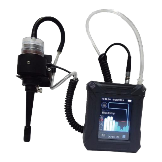
Overview of the HD-7204 Ease of use • The user controls all functionality and programming using menus displayed on color touch screen. • The compact unit clips to the workers belt or pocket allowing for flexibility during on-site monitoring. • A detached sensor head easily attaches to the worker for true OSHA defined breathing zone measurements. - Page 13 DustComm Pro Software The HD-7204 comes equipped with DustComm Pro software, which allows the user to look at real- time concentrations and graphs and internally store data to be downloaded to a PC for further analysis DustComm Pro software is designed for more detailed analysis of sampled data. Pull down menus provides a user-friendly environment to store and analyze data and print management ready reports.
-
Page 14: Features Of The Hd-7204
Features of the HD-7204 Introduction The HD-7204 provides a unique combination of features to provide superior data quality, ease of use, and flexibility to the user. Below is a partial list of distinctive features. Real-time display of • Particulate exposure levels •... - Page 15 Data management • Choice of 1 second, 4 sec, 10 sec or 60 seconds averaging/storage intervals. • Up to 15 days of stored data • Memory storage of up to 43,000 data point or 15 days of storage. • DustComm Pro Software supplied with a micro USB cable for downloading data to a PC. Data translation importable into Excel.
-
Page 16: Specifications Of The Hd-7204
Specifications of the HD-7204 Introduction The HD-7204 meets the following specifications. Specifications SPECIFICATION RANGE Calibration NIOSH 0600 with SAE Test Dust Accuracy + 10% Precision 0.02 mg/m Sensing range 0.001-500 mg/m3 or 1-500,000 ug/m3 0.1 to 10 m Respirable Particle size range 0.1 to 50 m Thoracic 0.1 to 100 m Inhalable (IOM) Recording time... -
Page 17: Components Of The Hd-7204
Components of the HD-7204 Components The following components ship with the HD-7204. • HD-7204 Monitor. • Hard Carrying Case • Battery charger with US, UK, Asia, and European adapters • Detachable Thoracic sampling inlet. • Opaque filter cassette holder. • HD-7204 Multi Media USB Drive, Including: DustComm Pro Software and the Instruction Manual. -
Page 18: Section Two
2. Section Two Operating Parameters of the HD-7204... -
Page 19: Section 2- Operating Parameters Of The Hd-7204
Section 2- Operating Parameters of the HD-7204 Introduction This section describes the steps involved in starting the HD-7204 and configuring its operating parameters. This section contains the following topics. • Turning the HD-7204 on and off…..Page 20 • Using the Menu……………………...Page 21 •... -
Page 20: Turning The Hd-7204 On And Off
Turning the HD-7204 ON and OFF Introduction The battery must be fully charged before each use. See Page 82 for information on battery maintenance. Power-ON 1. Press the ON/OFF key to turn the HD-7204 monitor On. The unit will turn on and the Splash Screen will appear. -
Page 21: Using The Menu
Using the Menu Introduction The HD-7204 Main Menu appears on the color touch screen display once the instrument is powered Note: See Appendix A for menu option flow charts. Accessing the Main Menu The HD-7204 is operated using the following main menu. The “Status Bar”... - Page 22 On Screen Programming through the Main Menu Naming Data Sets 1. Upon turning the device on for the first time, the run title will be empty. Press the Run Title to enter the name of a data set. Note: When the device is powered off then turned back on; the last-named data set will appear as the Run Title.
-
Page 23: Creating Unique Aerosol Profiles
Creating Unique Aerosol Profiles Introduction Pressing the Aerosol selection will allow users to create unique aerosol profiles. Each profile can contain the following entries: Name Particle Size Flow Calibration Factor Engineering Units of Measurement Celling Alarm STEL Alarm. 1. After selecting the Aerosol section, Press the Pen Icon to edit the Aerosol. The factory default of the HD-7204 offers a place holder for unique Aerosol entries by listing Aerosol 1-16. -
Page 24: Cross Calibration
Cross Calibration Introduction The Aerosol entry also allows for users to enter a Cross Calibration Factor. Real Time Nephelometers are calibrated with a standardized test dust. Test dust varies; however, a commonly used test dust is the ISO12103-01A2 Fine Test Dust, or “Arizona Road Dust.” The particle characteristics and properties of aerosol at the application site will vary from the test dust, causing a variance in the instrumentation response. -
Page 25: Selecting Language
Selecting Language Introduction The language is pre-set to English. It may be necessary to change the language based on the ultimate country of destination. Selecting Language 1. From the Home Page select the “Language” Option. (The language options are: English, French, German, Spanish, and Chinese.) Press the green check mark to save or press the back button to exit without saving changes. -
Page 26: Setting The Alarm
Setting the Alarm Introduction An audible alarm can be set to alert the worker of approaching threshold limits. Alarm settings The concentration level should be set to the defined agency standard for the particulate type being sampled or users preference. Using the alarm 1. - Page 27 Note: The maximum alarm value for mg/m3 is 500 mg/m3. If the user requires monitoring over 500mg/m3 th3 ug/m3 unit of measurement must be selected. The HD-7204 will display the max value. When sampling in ug/m3 the maximum concentration rage is 500,000 ug/m3. Users cannot select over this.
-
Page 28: Setting Date And Time
Setting Date and Time Introduction The date and time is pre-set by the factory to Eastern Standard Time. It may be necessary to change the date and time due to local time zones, daylight savings time or as preferred for a specific geographical location. - Page 29 3. Select the desired option and press the green check mark to save or press the back button to exit without saving changes. Setting Date and Time 1. From the Home Screen Select “Settings” Icon. Then scroll down and select Date and/or Time. 2.
-
Page 30: Setting Log Rate
Setting Log Rate Selecting Log Rate: From the Main Menu select “Log Rate” Select the desired log rate. Stated after each option is the approximate memory available for each desired selection. 1 Second ~ 12 hours 4 seconds ~ 25 hours 10 seconds ~ 60 hours 60 seconds ~ 15 days Note: When the data storage memory is low, a message will appear. -
Page 31: Data Recording
Data Recording Introduction Each data set can either be saved (preserved) or erased and rerecorded with each new data set. Data Recording Options 1. From the “Settings” menu press “Data Recording” The select either “Preserve Logs” or “Overwrite.” Press the green check mark to save or press the back button to exit without saving changes. -
Page 32: Data Management
Data Management Introduction The memory of the HD-7204 can be cleared at any time. There are several options for erasing data. Data Deletion erases all previously recorded data sets while maintaining Run Titles and other unique customer entries. Data Deletion 1. - Page 33 Clear Run Clearing the run will erase all the data sets similar to preforming a Data Deletion. The difference is Clearing the Run will also delete customers unique entries like Run Title, Aerosol entries and Calibration Spans. Think of the Clear Run function as a factory default. Overwriting Data Sets From the Home Screen Select “Settings”...
-
Page 34: About Screen
About Screen Introduction The about screen sates the Company, Model, Serial Number, Firmware and last Service/Calibration Date. -
Page 35: Section Three
3. Section Three Operating the HD-7204... -
Page 36: Section 3- Operating The Hd-7204
Section 3- Operating the HD-7204 Introduction This section describes and diagrams operation procedures of the HD-7204. This section contains the following topics. • Connecting the Sensor………………..Page 37 • Selecting the Particle Size…………… Page 38 • Particulate Selection………………..Page 39 • Thoracic Dust Particulates…………... Page 40 •... -
Page 37: Connecting Sensor
Connecting Sensor Introduction To connect the sensor, the signal cable must be attached the instrument. Sensor Connection 1. Line the red circle on the black signal cable to red dash on the mating connector found on the top of the HD-7204. The connection is very easy when aligned properly. 2. -
Page 38: Selecting The Particle Size
Selecting the Particle Size Introduction The inlet system of the HD-7204 can be configured to sample Thoracic, Respirable, or Inhalable or custom dust particulates. The following pages detail the selection process for each of these particle types. Inlets The table below lists the particulate type, agency standard, and required inlets. Particulate Standards Required Inlet... -
Page 39: Particulate Selection
Particulate Selection particles. Attach the desired sampling inlet to HD-7204 air sensor. See Instructions on the following pages to insert sampling inlets. Then, follow the steps below to select the desired size fraction. Creating an Aerosol Profile. 1. From the Main Menu press “Aerosol”. From the Aerosol list press the pen to create a new Aerosol Profile. -
Page 40: Thoracic Dust Particulates
Thoracic Dust Particulates Inserting the Thoracic Sampling Inlet 1. Select Thoracic from the Aerosol library on the instrument. See page 39 for further details. 2. Push the Thoracic sampling inlet into the bottom of the HD-7204 sensor assembly. 3. Attach the filter cassette to the top of the sensor. 4. -
Page 41: Respirable Dust Particulates
Respirable Dust Particulates Inserting the Cyclone for Respirable Sampling The GS-3 Cyclone for Respirable Sampling requires a cyclone adapter (part number GSA-204). The GS-3 Cyclone should have the GSA-204 adapter already inserted. If not insert the GSA-204 into cyclone as shown. 1. -
Page 42: Inhalable Dust Particulates
Inhalable Dust Particulates Inserting the IOM for Inhalable size fraction. 1. Select Inhalable from the Aerosol library. See page 39 for further details. 2. The SKC IOM is factory installed on the sensor. Simply remove any sampling inlets, if attached. 3. - Page 43 Orientation of the 25mm IOM for Inhalable size fraction 1. Remove HD-7204 sensor from lapel bracket by unclipping sensor cable and tubing from plastic clips on back of lapel bracket and removing the two black knurled thumbscrews as shown in Figure 1 below. Remove existing sampling inlet if any are attached. Retaining Clips Sensor...
- Page 44 2. Place IOM front plate adapter ring (P/N IA-204) over Inhalable Sampling Head IOM cassette front (P/N IS-104). Press on firmly to ensure cassette front makes firm and even contact with gasket on inside of adapter ring. Using provided hex wrench, tighten four (4) set screws on outside of adapter ring.
-
Page 45: Flow Rate
Flow Rate Introduction The flow rate will automatically adjust when selecting Respirable Thoracic and Inhalable as follows: Respirable 2.75 LPM Inhalable 2.0 LPM Thoracic 2.0LPM Calibrating Flow Rate To calibrate flow, select “Calibrate” from the main menu. Then select “Pump Flow” use to change the flow. - Page 46 Compression Fitting Black Release FA-104 Flow Adapter Includes: Metal Figure 3-7. P/N FA-104 Inserted into Sensor Stub and Tubing Figure 3-11.P/N FA-104 Inserted into Sensor Connection from HD-7204 to top of sensor assembly Connection from HD-7204 to chek-mate or flow meter Figure 3-12.
- Page 47 Custom Flow Rate The HD-7204 also offers a custom entry. By pressing “Particle Size” then selecting “Custom” users can enter a desired flow rate. The flow can be verified by flow meter of choice.
-
Page 48: Zero Calibration
Zero Calibration Introduction The Zero Calibration commonly referred to as the Auto-Zero sets the measurement baseline of the HD-7204 to zero mg/m or ug/m3 depending on user selection. Preform Auto Zero prior to collecting a new data set. Inserting the Zeroing Filer The Auto Zero function is based on a Pass/Fail system approach. - Page 49 Zero Calibrate Function 1. From the Main Menu press “Calibrate” Then press “Zero” 2. After inserting the zeroing filter as shown on Page 48, select the green check mark to continue. 3. The Zero Calibration screen will appear and run the auto zero for 50 seconds. When three stable readings taken together the in Zero Calibrate will be successful While the Zero Calibration is in active mode, the number of stable reading will be displayed.
-
Page 50: Sampling Procedure
Sampling Procedure Once you have selected a Particle Size, inserted the appropriate sampling inlet and completed the Auto-Zero process, the HD-7204 is ready to begin sampling. The following conditions should be met before starting the sampling process. Condition... For further Information See Page... -
Page 51: Real-Time Data Viewing
Real-Time Data Viewing Introduction The HD-7204 offers a real time rolling graphical display and statistics during sampling. Real- Time Rolling Graphical Display There are three viewing options for looking at real-time data. Ten Second Graphical Display. Upon starting a sample, the user will be automatically brought to the first of the three viewing options. The first is a 1 second rolling graph. -
Page 52: Stop Run
Stop Run STOP RUN To stop sampling, press the Stop Icon. A prompt will appear asking if the user really wishes to stop sampling. In order to access other menu options, the user most stop sampling. -
Page 53: Infield Calibration Verification
• If the HD-7204 is dropped or otherwise damaged. • The first time you use the instrument to double check the factory calibration. Note: The HD-7204 should be sent into EDC annually for recalibration. The following conditions must be met before checking the calibration span. - Page 54 2. Press “Calibrate” from the home screen. Then Press “Span” 3. The HD-7204 will then prompt the user to insert the CS-7204. 4. The instrument will then start the verification process and enter the Sensor Span Check screen. The process takes 30 seconds. Once complete the instrument will display a pass or fail. 5.
-
Page 55: Faults
Faults Introduction The HD-7204 will fault if the pump is not working properly or the battery is low. Flow Faults The pump will fault is there is kinked tubing or overloaded sample and can no longer sample with +/- 5% pump. If the event is sustained for 3-10 seconds pump will enter flow fault mode and Stop running. -
Page 56: Reviewing Stored Data
Note: When viewing history, the faults will be indicated for each date set as a numerical value listed under “Events.” The HD-7204 does not differentiate between a pump fault and a battery fault. Reviewing Stored Data Introduction Introduction The HD-7204 provides the user to view sample run statistics contained within individual data sets. How to Review Stored Data 1. -
Page 57: Uploading Data
Uploading Data Introduction In order to upload Data the HD-7204 must be connected to a computer using the Micro USB provided. The data will upload from the instrument to the HAZCOMM Pro Software. The upload will only work on Windows 10. It is not supported on earlier versions on Windows. Uploading Data Procedure 1. -
Page 58: Live Feed
Live Feed Introduction The HD-7204 offers a live feed option. This option will allow users to graph and see real-time concentration values and graphing on a PC. This feature requires the device to be hardwired to a PC or laptop unless wireless options were purchased with the instrument. Note: In order to download the live feed data has to be turned off. - Page 59 Live Feed Used with optional Wireless Radio data modems 1. On the “Unit” pull down window of the DustComm Pro software Feature select “Live Feed.” 2. Connect optional Wireless mode of communication. 3. Select “Record”...
-
Page 60: Section Four
4. Section Four Dustcomm Pro Software... -
Page 61: Section 4- Using Dustcomm Pro Software
Section 4- Using DustComm Pro Software Introduction This section describes how to operate DustComm Pro Software. This section contains the following topics. • Introduction to DustComm Pro Software .………. Page 62 • Installing DustComm Pro Software……………… Page 63 • Loading DustComm Pro Software……………….. Page 64 •... -
Page 62: Introduction To The Dustcomm Pro Software
Introduction to the DustComm Pro Software Introduction DustComm Pro is a powerful and flexible Windows application software package designed for use with the Haz-Dust Particulate Monitoring Equipment. DustComm Pro is both communications software that enables stored project data to be downloaded to a PC, and a data manipulation tool, enabling detailed analysis and reporting of sampled data. -
Page 63: Installing Dustcomm Pro Software
Installing DustComm Pro Software Introduction DustComm Pro installation is easy and quick, the entire process should take less than 5 minutes. NOTE: When the HD-7204 will only work with Windows 10. When installing the DustComm Pro error popups will appear at different times during the installation process. Please proceed. Windows 10 had a change in design, meaning that the Operating System now recognizes all software that is not Microsoft Software. -
Page 64: Loading Dustcomm Pro Software
Loading DustComm Pro Software Figure 4-2.DustComm Pro Screen immediately after loading software... -
Page 65: Menu Selections
Menu Selections Introductions Figure 4-3 through Figure 4-5 show each of the DustComm Pro menu options. Note: If a menu option is displayed in light type it is not available during the current task. Opens Saved Files Saves Current Open Files if changed Saves Current Open Files, that have not yet been saved Closes Open Files Saves Current Open Files as a text file, so that you can open the data... -
Page 66: File Menu Commands
File Menu Commands Introductions Use the File Menu option to open, save, print, close and export sampled data. You can also use the File Menu to Exit the DustComm Pro Software Notes: • Data is sorted by time collected. • Data points are reported in mg/m Opening an Existing Project Folder Follow the steps in the table below to retrieve stored project data. -
Page 67: Downloading Data
Internally stored data can be downloaded to DustComm Pro for detailed analysis. Downloading Data The three major steps used to download data from the EDC dust-monitoring unit to a PC are listed below and detailed in the next few pages. - Page 68 2. Select Download. 3. Select To Dust Data Collector. Press ENTER. Result: The Transmitting window appears. Note: Bars on the PC screen should increase as the unit downloads. When the transmission is complete... • The To Dust Data Collector selection screen is displayed on the units display. The unit may be shut off at this time.
-
Page 69: Dustcomm Pro Windows
DustComm Pro Windows Introductions Each section of the DustComm Pro Window will explain a different part of the statistics. Location Information The Location information will give you general details about the downloading statistics. Such as date, time, start/stop time, data rate, duration, how many samples where downloaded and the unit. There is also box so that you can name the location and a shortcut to type in any notes you would like to add. - Page 70 Quick Plot The Quick Plot graph shows you a miniature version of the Full Plot. The Full Plot button is located directly below Quick Plot. Figure 4-12. Quick Plot & Full Plot Button on the DustComm Pro Window. Location Data The location data section shows you the milligrams per cubic meter you sampled for and the times that they were sampled at.
-
Page 71: Translating Data To An Ascii Text File
Translating Data to an ASCII Text File Introductions Project Data must be translated into .CSV format before it can be read by a spreadsheet application. Translating Data Follow the steps in the table below to Translate Project Data into ASCII Text format. Note: A Project Folder must be open to access the translate feature. -
Page 72: Generating A Plot
Generating a Plot Introductions A graph can be plotted with full plot located at the bottom of the DustComm Pro Window. Generating a Graph Follow the steps in the table below to generate a graph using the DustComm Plot menu selections. 1. -
Page 73: Data Plot Menu Selections
Data Plot Menu Selections Introductions At the top of the data plot will be a button bar. Below is an explanation of what each button does. 4 5 6 7 8 9 10 11 1 2 3 Number Function Saves plotted information as a DustComm Pro Chart (*.dcc). Copies plot to a bitmap file. - Page 74 1 2 3 4 5 6 7 8 11 12 13 14 15 16 17 18 19 20 21 Number Function Pointer tool. Insert Squares. Insert Ovals. Insert arrows. Insert arched lines. Insert a picture. Choose the size of your picture and then right click on the box and select properties.
-
Page 75: Editing Title
Editing Title Introductions A customized title can be added to a graph before printing. Editing the Title 1. Have location plotted already. Select the Edit Title button on the menu bar. 2. A Window will appear where you can edit the title for what you would like its name to be. 3. -
Page 76: Applying A Correction Factor
Applying a Correction Factor Introductions A correction factor can be applied to the data collected with the EDC unit to account for variances in gravimetric readings. Calculating a Correction Factor The correction factor is calculated by dividing the Gravimetric reading by the EDC unit reading. -
Page 77: Inability To Download Data To Pc
Inability to Download Data to PC Introductions If DustComm Pro Software installs properly but downloading instrument to computer is unsuccessful try the following: • Ensure that the USB cable is secure into the side of the instrument and the PC. •... -
Page 78: Section Five
5. Section Five Maintenance of the HD-7204... -
Page 79: Section 5- Maintenance On Hd-7204
Section 5- Maintenance on HD-7204 Introduction This chapter covers the maintenance procedures for the HD-7204. This section contains the following topics. • Checking the Calibration Span.………………Page 80 • Battery Maintenance………….. …………….Page 82 • Determining Battery Charge Status………… Page 82 • Charging the Battery……………………….. Page 83 •... -
Page 80: Checking The Calibration Span
• If the HD-7204 is dropped or otherwise damaged. • The first time you use the instrument to double check the factory calibration. Note: The HD-7204 should be sent into EDC annually for recalibration. The following conditions must be met before checking the calibration span. - Page 81 7. Press “Calibrate” from the home screen. Then Press “Span” 8. The HD-7204 will then prompt the user to insert the CS-7204. 9. The instrument will then start the verification process and enter the Sensor Span Check screen. The process takes 30 seconds. Once complete the instrument will display a pass or fail. 10.
-
Page 82: Battery Maintenance
• Do not operate pump from or charge pump in hazardous locations. • Power off pump before removing battery to avoid loss of time, date, and other settings. • Use only the EDC approved battery pack (P/N BP-7204) an unapproved battery and/or could damage the pump and will void any warranty. -
Page 83: Charging The Battery
Charging the Battery Charge the battery under the following conditions using only the supplied and or approved EDC charger. Note: a fully charged new battery will last 22 hours at 2 LPM without a filter at 70F (21 C). -
Page 84: Cleaning Sensor Optics
Removing the Battery Pack 1. Remove the two screws from the battery pack housing. Wiggle the housing and pull out. 2. The battery is attached to the instrument by a black plastic connector. Depress the latch to release connection. Keep battery in tray. Do not remove battery. The entire battery pack needs to be replaced, or warranty is void. -
Page 85: Cleaning Sensor Optics
Cleaning Sensor Optics Description: A dirty optical sensor can affect the readings of the instrument and should be cleaned periodically. Note: Cleaning should be performed after every 8.0 hours of use when monitoring in average concentrations of over 1 mg/m³. Step 1. -
Page 86: Appendix
Appendix... - Page 87 Appendix A NIOSH/OSHA Particulate Air Monitoring Reference Dust/Hazard Agency Reference TWA STEL alpha-Alumina (Respirable fraction) OSHA 5 mg/m alpha-Alumina (Total dust) OSHA 15 mg/m Aluminum, Pyro powders OSHA Aluminum (Respirable fraction) 5 mg/m Ammonium nitrate OSHA Ammonium sulfamate (Respirable dust) OSHA 5 mg/m Ammonium sulfamate (Total dust)
- Page 88 Dust/Hazard Agency Reference TWA STEL Copper dust NIOSH 7029 1 mg/m Copper, Dusts & Mists OSHA ID 125G 1 mg/m Copper, Dusts & Mists OSHA ID 121 1 mg/m Copper (Elements) NIOSH 7300 1 mg/m Copper fume NIOSH 7029 0.1 mg/m Copper fume OSHA ID 121...
- Page 89 Dust/Hazard Agency Reference TWA STEL Lead NIOSH 7082 <0.1 mg/m3 Lead NIOSH 7105 <0.1 mg/m3 Lead NIOSH 7700 <0.1 mg/m3 Lead (Elements) NIOSH 7300 <0.1 mg/m3 Lead, Inorganic fumes & dusts (as Pb) OSHA ID 121 0.05 mg/m3 Lithium (Elements) NIOSH 7300 25 g/m3...
- Page 90 Dust/Hazard Agency Reference TWA STEL Total nuisance OSHA 15 mg/m Total nuisance (Particulates) NIOSH 0500 10 mg/m Rouge (Respirable dust) OSHA 5 mg/m Rouge (Total dust) OSHA 15 mg/m Silica, Amorphous OSHA 20 mppcf Silica, Crystalline tripoli, Respirable dust OSHA ID 142 0.05 mg/m Silicon carbide (Respirable dust)
- Page 91 Appendix B Introduction The tables below show the particle size cut point for Thoracic, Inhalable, and Respirable dust particles. Particle Size Selections Inhalable Respirable Particle Inhalable Particle Respirable Aerodynamic Particulate Mass Aerodynamic Particulate Mass (IPM) (%) Diameter (m) (RPM) (%) Diameter (m) 54.5 52.5...
- Page 92 Appendix C Glossary of Terms Term Definition/Standard m Micron, 1/1000 of a meter. Arizona Road Dust Inhalable Dust Particulates having a 50% cut point at 100m. Particulates Liters per minute. mg/m Milligrams per cubic meter. NIOSH National Institute of Occupational Safety & Health OSHA Occupational Safety &...
- Page 93 Accessory Part Number Battery Charger BC-750 Li Ion Battery Pack BP-750 37 mm Opaque Filter Cassette Blanks CAS-102 37mm MCE 0.8um filter (pack 50) EDC-1931A Calibration Reference CS-7204 Cleaning Kit KKB-101 Carrying Case CC-104 Flow Meter FM-105 IOM Sensor Inlet...
Need help?
Do you have a question about the HAZ-DUST HD-7204 and is the answer not in the manual?
Questions and answers