Table of Contents
Advertisement
Quick Links
Advertisement
Table of Contents

Related Manuals for edc MU300


Summary of Contents for edc MU300
- Page 1 User’s Manual Operating Instructions of Ultrasonic Flowmeter...
- Page 2 Preface Thanks for purchasing the product! The User’s Manual covers functions, settings, wiring and troubleshooting methods of this flowmeter. Please carefully read this manual before use. After reading the manual, please keep it in a proper place for reference when you operate the flowmeter. Notes Any modifications concerning function update in this manual will not be notified.
-
Page 3: Table Of Contents
Pipe Design and Selection ....................15 Transducer Installation ....................18 Chapter VI Operation ......................... 25 Common Functions ......................25 Description of Operation Menus ..................30 Menu Configuration ......................32 Chapter VIII Communication Interface and Communication Protocol ..........47 MU300 Rev1.0 Oct20 Page 1 of 54... - Page 4 MU300 Rev1.0 Oct20 Page 2 of 54...
-
Page 5: Product Liabilities And Quality Assurance
Please DO pay attention to this symbol. Any slight negligence may cause severe health hazard and may damage the flowmeter or related equipment and facilities in operation. Prompts! The symbol indicates related important information for operation. MU300 Rev1.0 Oct20 Page 3 of 54... -
Page 6: Safety Instructions To Operators
When removing the flowmeter, please follow the fluid OEM’s safety instructions to avoid splashing. Pay attention to the flowmeter’s probe. Even a minor scratch or incision would influence its accuracy. To get the optimum efficiency, the longest calibration period could not exceed two years. MU300 Rev1.0 Oct20 Page 4 of 54... -
Page 7: Chapter Ii Descriptions Of The Flowmeter
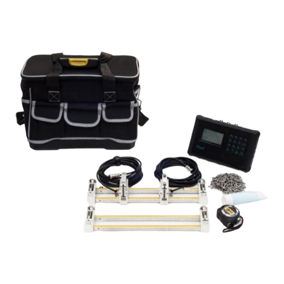
Please check the flowmeter’s nameplate and conform whether the scope of supply is identical with your order. Check whether the power information on the nameplate is correct or not; if not, please contact the manufacturer or the dealer. MU300 Rev1.0 Oct20 Page 5 of 54... - Page 8 1. Carrying Case*1pc. 2. Transmitter (Electronic)*1pc. 3. Transducer (Sensor) *1 pair. 4. Mounting track *1 set DT 5. Pipe straps *2 pairs. 6. Coupling compound (Grease)*1 pc, Battery charge*1pc, Output cable*1pc and Tapeline*1 MU300 Rev1.0 Oct20 Page 6 of 54...
-
Page 9: Measuring Principle
(super small diameter), juice flow measurement, milk flow measurement, and so on. MU300 Rev1.0 Oct20 Page 7 of 54... -
Page 10: Nameplate
Check whether the power supply on the nameplate is correct or not. The following shows information on the nameplate: Ultrasonic Flowmeter Max. Operating Model: Temperature ℃ Specification Pressure Rating Power Supply Meter Factor Accuracy Class Measuring Range Output Product No. MU300 Rev1.0 Oct20 Page 8 of 54... -
Page 11: Connecting Electrical Cables
The measuring transducer must be well grounded according to related standard DESIGN CODE OF INSTRUMENT GROUNDING (HT/T 20513-2014). The ground conductor shall not transmit any disturbance voltage. The ground conductor is not allowed to connect other electrical equipment. MU300 Rev1.0 Oct20 Page 9 of 54... -
Page 12: Transmitter Connections
DO always finish all tasks when running. No matter in any displays, tasks including measurement and output should be finished as usual. MU300 Rev1.0 Oct20 Page 10 of 54... -
Page 13: Chapter Iv Operation Panel And Quick Start
Flow Rate Flow Rate Prompts! "*R" indicates that the flowmeter is running normally; “D” indicates that the flowmeter is carrying out gain setting; “E” indicates that the flowmeter can’t receive any ultrasound signals. MU300 Rev1.0 Oct20 Page 11 of 54... - Page 14 ENTER again to recover display. Note: When using the heat function, the temperature difference displayed is positive, while using the cold function, the temperature difference displayed is negative. MU300 Rev1.0 Oct20 Page 12 of 54...
-
Page 15: Keyboard Operation
If you need to correct the flowmeter parameters, please firstly switch to related menu, find out the parameter you want to correct and then press [Enter] to confirm; input the data and then press [Enter] to confirm your corrections. MU300 Rev1.0 Oct20 Page 13 of 54... -
Page 16: Chapter V Installation
To ensure reliable installation, DO take the following measures: Before installing the flowmeter, DO consider of the flowmeter’s diameter, pipe size and installation position. Correct installation could ensure accurate output signals, less maintenance and maximum performance. MU300 Rev1.0 Oct20 Page 14 of 54... -
Page 17: Pipe Design And Selection
Each flowmeter should have a nameplate clearly identifying its certifications. Please DO install and use the flowmeter according to the explosion-proof grade and protection grade as shown on the nameplate. MU300 Rev1.0 Oct20 Page 15 of 54... - Page 18 General conditions Install after the elbow MU300 Rev1.0 Oct20 Page 16 of 54...
- Page 19 The measurement point should be in the pipe section with relatively new inner wall with no or relatively less scaling. The pipe must be made of compact material. When selecting the installation point, DO ensure no welding seams or other gaps. MU300 Rev1.0 Oct20 Page 17 of 54...
-
Page 20: Transducer Installation
L of the installation spacing in M14 menu. Installation spacing of the clamp-on transducer should be the distance between its two end surfaces; while that of the insert-in transducer should be the distance between the axis center of two transducers. MU300 Rev1.0 Oct20 Page 18 of 54... - Page 21 Z-shape installation method on the more complicated site and large-diameter pipes. Pipe top Pipe top Pipe bottom Pipe bottom Z-shape Installation of Clamp-on Transducer Z-shape Installation of Insert-in Transducer MU300 Rev1.0 Oct20 Page 19 of 54...
- Page 22 The arrows on transducers must be identical with the fluid direction User’s pipe Upstream straight pipe Downstream straight pipe L2 Installation spacing(mm) Fluid direction Schematic Diagram of V-shape Installation of Clamp-on Transducer MU300 Rev1.0 Oct20 Page 20 of 54...
- Page 23 Step 2. Turn off the ball valve and tighten it on the mounting base. Step 3. Rotate the lock nut and loosen the lock ring, retract the transducer into the connecting nut and then tighten the connecting nut on the ball valve. MU300 Rev1.0 Oct20 Page 21 of 54...
- Page 24 User’s pipe Pipe drillhole diameter (mm) Downstream straight Upstream straight pipe L2 pipe L1 Fluid direction Installation spacing (mm) Drillhole diameter (mm) Schematic Diagram of V-shape Installation of Insert-in Transducer MU300 Rev1.0 Oct20 Page 22 of 54...
- Page 25 Schematic Diagram of Z-shape Installation of Insert-in Transducer 5.3.5 Confirmation on Installation Quality On the operation panel, press [Menu]+[4] to enter 04 menu. Status Signal Sound Time 80.0 80.1 MU300 Rev1.0 Oct20 Page 23 of 54...
- Page 26 Under normal conditions, the fluctuation of time difference should be less than ±20%. But when the pipe diameter is too small or the flow rate is extremely low, its fluctuation would exceed the normal value a little. MU300 Rev1.0 Oct20 Page 24 of 54...
-
Page 27: Chapter Vi Operation
You need to set zero point to improve the accuracy for small flow measurement. At the time, you need to cut zero point on site. MU300 Rev1.0 Oct20 Page 25 of 54... - Page 28 -1,000 ~ 0 ~ 2,000m3/h, and 20 ~ 4 ~ 20mA output is used while not considering the flow direction, you could set 1000 and 2000 as the minimum and maximum limit values respectively in M32 menu. MU300 Rev1.0 Oct20 Page 26 of 54...
- Page 29 How to set? For example 1: It requires the relay outputs alarm signals when the transient flow exceeds 300~1,000m3/h, settings are as follows: (1) Menu 35, Alarm 1#, lower limit300; (2) Menu 35, Alarm 1#, upper limit1,000; (3) Menu 34, Relay Settings-Options-Alarm 1#. MU300 Rev1.0 Oct20 Page 27 of 54...
- Page 30 = + 3.520580E+02 m3 e = +3.520580E + 02 m3 f = +0.000000E+00 m3 g = +0.000000E+00 GJ/h h = +0.000000E+00 GJ i = +0.000000E + 00 GJ j = + 0.000000E+00'C k = +0.000000E+00'Cfile MU300 Rev1.0 Oct20 Page 28 of 54...
- Page 31 You could view your flowmeter’s serial number in M 50 menu. Note: Please refer to “Details about Menus” for operation of other menus. MU300 Rev1.0 Oct20 Page 29 of 54...
-
Page 32: Description Of Operation Menus
21 low flow cut off 22 zero point settings 23 totalizar Calibration settings 24 temperature 25 power cut compensation 26 K factor 27 correction 28 SQA 30 serial port settings 32 current settings Input/output settings MU300 Rev1.0 Oct20 Page 30 of 54... - Page 33 61 running time Others 62 current calibration 63 RTD calibration Note: Options concerning temperature, cold/heat quantity and energy in the menu could be displayed if only the flowmeter is provided with cool (heat) meter functions. MU300 Rev1.0 Oct20 Page 31 of 54...
-
Page 34: Menu Configuration
Heat Press ENTER stop switching 30.0 (℃) continuously update Display the current items; Press ENTER again to 123.4 restore switching. Note: Only energy meter is provided with this function. MU300 Rev1.0 Oct20 Page 32 of 54... - Page 35 1482 be close to the sound velocity shown in M12 menu. If the difference is too big, you should Ratio 100% check the installation settings and whether it is properly installed or not. MU300 Rev1.0 Oct20 Page 33 of 54...
- Page 36 4.DIP (Ductile Iron Pipe) 5.Copper (Copper Pipe) Others 3200 6. Alu (Aluminum Pipe) 7. ACP (Asbestos Cement Pipe) 8. FPG (Fiberglass Pipe) 9. Others if you choose Item 9,please input the material velocity. MU300 Rev1.0 Oct20 Page 34 of 54...
- Page 37 Note: Room temperature is 20 ℃ by default. Transducer Transducer Settings Type Method Mode Select the transducer type: Options 0.Clamp D1 The following transducer types are available in the menu: 0. Clamped D1 2.Clamped D1U 3 Insert-In MU300 Rev1.0 Oct20 Page 35 of 54...
- Page 38 For example, if the cutoff value is set as 0.03, system will take all the measured flow velocity values from - 0.03 to + 0.03 as "0". Generally, 0.03 is recommended in most applications MU300 Rev1.0 Oct20 Page 36 of 54...
- Page 39 Set zero point deviation Enter a deviation added on the measured value to get the actual measured value. It is not recommended for clients to use by themselves or take it as the standard calibration method. MU300 Rev1.0 Oct20 Page 37 of 54...
- Page 40 : 0. Heat 1. Cold 2. All RTD settings Temperature Select temperature input source Source Sensitivity 0.RTD Options 0.RTD RTD indicates Pt1000 platinum resistance; Note: This menu is only applicable for energy meter. MU300 Rev1.0 Oct20 Page 38 of 54...
- Page 41 Each flowmeter would be calibrated before leaving factory to get its meter coefficient, Value 1.00 which we call the K coefficient. You also could calibrate the flowmeter in service on site through M26 menu. MU300 Rev1.0 Oct20 Page 39 of 54...
- Page 42 Statistic Analysis This is a technician menu. Please apply the Reset factory settings and DO NOT alter parameters Options 0.On in the menu. Value 0.000 Reset Options 0.Auto Value 0.000 MU300 Rev1.0 Oct20 Page 40 of 54...
- Page 43 4.38400 None RS485 5.56000 None Order Options a.1-0 : 3-2 AI Setting AI Settings Al1 The upper/lower limit input. LowerL AI2 The upper/lower limit input. UpperL 1000.0 AI Setting LowerL UpperL 1000.0 MU300 Rev 1.0 Oct20 Page 41 of 54...
- Page 44 3. Imp gal (Imperial Gallons) 4.mg (Million Gallons) cf (Cubic Feet) US bbl (USA Barrels) Imp bbl (Imperial Barrels) 8. Oil bbl (Oil Barrels) The following options are available: /Day/Hour/Min/Sec Factory setting is m3/h. MU300 Rev1.0 Oct20 Page 42 of 54...
- Page 45 (E + 2) g.x1,000 (E + 3) h.x 10,000 (E+4) a. x 0.001 (E-3) b. x 0.01(E-2) c.x 0.1(E-1) d. x 1(E+0) e. x 10(E+1) f. x 100(E+2) g. x 1000(E+3) h.x 10000(E+4) MU300 Rev1.0 Oct20 Page 43 of 54...
- Page 46 Time and Date Time and Date You could alter time and date in this menu. Time 13:10:34 20200101 Date Key Ton Key Tone You could choose to turn “on/off” the key Options 0.ON tone. MU300 Rev1.0 Oct20 Page 44 of 54...
- Page 47 In this menu, you could view historical data for Menu m³ a day in the past 31 days, or a month in the past 12 months or a year in the past six years. MU300 Rev1.0 Oct20 Page 45 of 54...
- Page 48 RTD Adjust RTD adjustment This menu is for RTD calibration. Enter to go 0℃ Note: The flowmeter would be calibrated Enter to go 180℃ before leaving factory, recommended for the user to calibrate it. MU300 Rev1.0 Oct20 Page 46 of 54...
-
Page 49: Chapter Viii Communication Interface And Communication Protocol
One data character string is used for indicating the basic command, while one ENTER is used for indicating ending the command. This command is applicable for RS232 and RS485. Common commands are shown below: Common Communication Commands MU300 Rev1.0 Oct20 Page 47 of 54... - Page 50 OCT Settings dddd.d(cr) return to "OK" if it is set correctly SRS(cr)(lf) Start Ration Control OK (cr) With check return command prefix Note 5 Network command prefix of digit string Note 6 address MU300 Rev1.0 Oct20 Page 48 of 54...
- Page 51 W and P commands could be combined for use, for example, W123PRT+, which means the network address it reads is the total value of No. 123 flowmeter, its feedback data are accumulated and checked. MU300 Rev1.0 Oct20 Page 49 of 54...
- Page 52 Slave feedback data frame format (function code 0x06): Operation Register’s first Number of Slave address Check code function code address registers 1 byte 1 byte 2 bytes 2 bytes 2 bytes 0x01~0xF7 0x06 0x0000~0xFFFF X0000~0xFFFF CRC Check code MU300 Rev1.0 Oct20 Page 50 of 54...
- Page 53 0x01 0x06 0x10 0x03 0x00 0x02 0xFC 0xCB Flowmeter’s address function code/Register address/Number of registers/ CRC check code Flowmeter’s feedback data: 0x01 0x06 0x10 0x03 0x00 0x02 0xFC 0xCB Flowmeter’s address function code/Register address/Number of registers/CRC check code MU300 Rev1.0 Oct20 Page 51 of 54...
- Page 54 Negative total–highword $000D 40014 Negative total – exponent 16 bits int. $000E 40015 NET Total-low word 32 bits real $000F 40016 NET Total –high word $0010 40017 NET Total –exponent 16 bits int. MU300 Rev1.0 Oct20 Page 52 of 54...
- Page 55 Al2 value-high $004c 40077 word $004d 40078 4~20mA value- low word 32 bits real Unit: mA $004e 40079 4~20mA value- high word Address list of single write register (Writing with 0x06 function codes) MU300 Rev1.0 Oct20 Page 53 of 54...
- Page 56 1."Kc"-Kilocalorie 2."MB"- MBtu 3."KJ"-Kilojoule 4."Bt" - Btu 5, "Ts"-US Tonnes 6."Tn"-US Tons 7."kw" –Kwh 16 bits int-indicates short integer, 32 bits int-indicates long integer, 32 bits real-indicates floating point number, String-indicates character string. MU300 Rev1.0 Oct20 Page 54 of 54...
Need help?
Do you have a question about the MU300 and is the answer not in the manual?
Questions and answers