Table of Contents
Advertisement
Quick Links
藍色線條為尺寸標示,請勿印刷上去!
© 2018 Thermaltake Technology Co., Ltd. All Rights Reserved. 2018.08
All other registered trademarks belong to their respective companies.
FOR HOME OR OFFICE USE
Questo manuale d'istruzione è fornito da trovaprezzi.it. Scopri tutte le offerte per
Curved Edition
o cerca il tuo prodotto tra le
125 mm
www.thermaltake.com
Tested To Comply
With FCC Standards
migliori offerte di Case e Alimentatori
C
ore
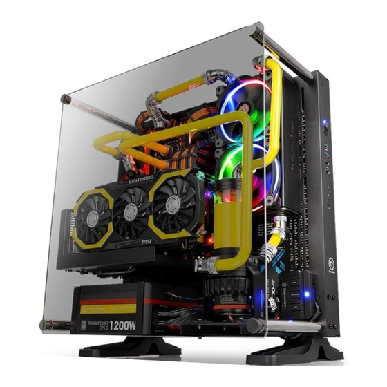
Thermaltake Core P3 TG
P
3
TG Curved
Your Build. Our Core
User's Manual
Benutzerhandbuch
Mode d'emploi
Manual del usuario
Manuale dell'utente
Manual do Utilizador
安裝說明書
用戶手冊
ユーザーズマニュアル
Руководство пользователя
kullanıcı elkitabı
(EEE Yönetmeliğine Uygundur)
คู ่ ม ื อ การใช้
www.thermaltake.com
刀模
Advertisement
Table of Contents

Related Manuals for Thermaltake Core P3 TG Curved


Summary of Contents for Thermaltake Core P3 TG Curved
- Page 1 ユーザーズマニュアル Руководство пользователя kullanıcı elkitabı (EEE Yönetmeliğine Uygundur) คู ่ ม ื อ การใช้ © 2018 Thermaltake Technology Co., Ltd. All Rights Reserved. 2018.08 All other registered trademarks belong to their respective companies. www.thermaltake.com Tested To Comply With FCC Standards FOR HOME OR OFFICE USE www.thermaltake.com...
- Page 2 LCS chassis should be held to. The Tt LCS certification was created so that we at Thermaltake can designate to all power users which chassis have been tested to be best compatible with extreme liquid cooling configurations to ensure you get the best performance from the best features and fitment.
-
Page 3: Table Of Contents
CPU cooler height limitation: 180mm Case LED connection VGA length limitation: 280mm (With Reservoir & Radiator) Clearance 450mm (Without Reservoir & Radiator) USB 3.0 connection PSU length limitation: 200mm Audio connection Thermaltake Power Supply Series (Optional) Tt RGB Plus Ecosystem... -
Page 4: Accessory
TG part list Accessory Figure Q'ty Parts Name Used for Curved Tempered Glass Side Panel Core P3 Figure Q'ty Parts Name Used for PSU, PSU Bracket, Screw#6-32 x 6mm VGA Module Rubber 18 x 7 mm Side Panel Nut Setter Stand-off Rubber 18 x 1.5 mm Side Panel... -
Page 5: Warning And Notice
Warning and Notice Atenção!! Limite de altura para o dissipador do CPU: O limite de altura para o dissipador do CPU é 180 mm (7,1 polegadas). Limite de comprimento para VGA (placa gráfica): O limite de comprimento para VGA (placa gráfica) é 280 mm (11 polegadas). 警告!!... -
Page 6: Side Panels Disassembly
Power Supply Unit (PSU) Installation Side Panels Disassembly Type A Compatible With ATX Motherboard Español / 1. Instale la PSU en la ubicación correcta. 2. Ajuste el puente de soporte de la PSU en la ubicación adecuada y asegúrela con tornillos. Italiano / 1. -
Page 7: Motherboard Installation
Motherboard Installation 3.5" & 2.5" HDD Installation 3.5” HDD Locking clips For 3.5" HDD: Secure 3.5" HDD from both side of the HDD tray by locking clips. 2.5” HDD Remove this locking clip For 2.5" HDD: Secure 2.5" HDD from the bottom of the HDD by screws. -
Page 8: Pci Card Installation
PCI Card Installation Type B Italiano / Interior 1. Estrarre il vano HDD. Direct installing to Motherboard 2. Posizionare il disco fisso da 2,5” o 3,5” nel Type A vano e fissarlo con le viti. 3. Fare scorrere l’HDD indietro verso la struttura a gabbia HDD. -
Page 9: Liquid Cooling Installation
Liquid Cooling Installation Extend installing to Motherboard Type B Left Side: 3 x 140mm 3 x 120mm Install Riser Cable by screws 2 x 140mm Left 420mm 360mm 280mm... -
Page 10: Window Panel Installation
Window Panel Installation Chassis Installation - Horizontal Horizontal Usage Way 1 Fix foot-stand by screws Way 2 Chassis Installation Wall-mounting Wall-mounting Usage Screw Hole Dimension: M6 x 1 pitch (Bracket is not included) Wall-Mount Dimensions Unit: mm Chassis Installation -Vertical Vertical Usage Fix foot-stand by screws... -
Page 11: Chapter3 Leads Installation Guide
Leads Installation Français English Leads Installation Guide Guide d'installation des fils Case LED Connection / On the front of the case, you can find some LEDs and switch leads. Please consult your user Connexion des voyants du boîtier / Sur la face avant du boîtier, vous trouverez plusieurs voyants et les fils des manual of your motherboard manufacturer, then connect these leads to the panel header on the motherboard. - Page 12 Italiano 繁體中文 Guida di installazione dei contatti 線材安裝說明 Connessione del LED del case / Nella parte anteriore del case, sono presenti alcuni contatti per interruttori e LED. 機殼LED連接方式 / 在機殼前方的面板後面,可以找到一些LED與開關線材(POWER Switch….),請參考主機板使用說明書, Consultare il manuale utente del produttore della scheda madre, quindi connettere i contatti alla parte superiore del 並將機殼上的線材正確地連接到主機板上,這些線材通常都會印有標籤在上面,如果沒有的話,請找出機殼前方面板上線材原...
- Page 13 Türkçe 日 本 語 Ara Kablo Kurulum Kılavuzu リード線の取り付けガイド Kasa ışık bağlantısı / Kasanın ön kısmında bazı ışıklar ve anahtar ara kabloları görebilirsiniz. Lütfen anakart üreticinizin ケース LED の接続 / ケース前面には、LEDとスイッチリード線があります。 マザーボードメーカーのユーザーマニュアル sağladığı kullanım kılavuzuna bakın ve daha sonra, bu ara kabloları, anakart üzerindeki panel bağlantı noktalarına bağlayın. を参照し、これらのリード線をマザーボードのパネルヘッダに接続してください。...
Need help?
Do you have a question about the Core P3 TG Curved and is the answer not in the manual?
Questions and answers