Table of Contents
Advertisement
Quick Links
© 2020 Thermaltake Technology Co., Ltd. All Rights Reserved. 2020.05
All other registered trademarks belong to their respective companies.
Tested To Comply
With FCC Standards
FOR HOME OR OFFICE USE
www.thermaltake.com
C
P
8 TG
ore
User's Manual
Benutzerhandbuch
Mode d'emploi
Manual del usuario
Manuale dell'utente
Manual do Utilizador
安裝說明書
用戶手冊
ユーザーズマニュアル
Руководство пользователя
kullanıcı elkitabı
(EEE Yönetmeliğine Uygundur)
คู ่ ม ื อ การใช้
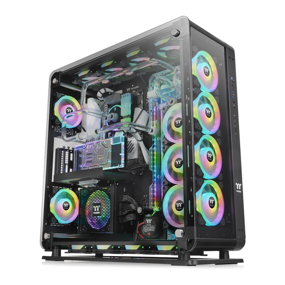
* Picture is for reference only
www.thermaltake.com
Advertisement
Table of Contents


Need help?
Do you have a question about the Core P8TG and is the answer not in the manual?
Questions and answers