Table of Contents
Advertisement
© 2014 Thermaltake Technology Co., Ltd. All Rights Reserved. A-2014.11
All other registered trademarks belong to their respective companies.
Tested To Comply
With FCC Standards
FOR HOME OR OFFICE USE
www.thermaltake.com
C
9
ore
Your Build. Our Core
User's Manual
Benutzerhandbuch
Mode d'emploi
Manual del usuario
Manuale dell'utente
Manual do Utilizador
安裝說明書
用戶手冊
ユーザーズマニュアル
Руководство пользователя
kullanıcı elkitabı
(EEE Yönetmeliğine Uygundur)
คู ่ ม ื อ การใช้
www.thermaltake.com
Advertisement
Table of Contents

Related Manuals for Thermaltake Core X9 - A-2014.11


Summary of Contents for Thermaltake Core X9 - A-2014.11
- Page 1 ユーザーズマニュアル Руководство пользователя kullanıcı elkitabı (EEE Yönetmeliğine Uygundur) คู ่ ม ื อ การใช้ © 2014 Thermaltake Technology Co., Ltd. All Rights Reserved. A-2014.11 All other registered trademarks belong to their respective companies. www.thermaltake.com Tested To Comply With FCC Standards FOR HOME OR OFFICE USE www.thermaltake.com...
-
Page 2: Table Of Contents
LCS chassis should be held to. The Tt LCS certification was created Liquid Cooling Installation so that we at Thermaltake can designate to all power Bracket Installation users which chassis have been tested to be best compatible with extreme liquid cooling configurations to 2.10... -
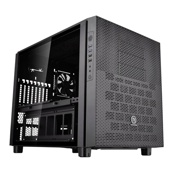
Page 3: Specification
Specification Warning and Notice Case Type E-ATX Cube Case Dimension (H*W*D) 502 x 380 x 640 mm (19.8 x 15 x 25.2 inch) Transparent Window Side Panel Material SPCC Front (intake) : Cooling System 200 x 200 x 30 mm fan (800rpm, 13dBA) <250 mm Rear (exhaust) : 120 x 120 x 25 mm Turbo fan (1000rpm, 16dBA) -
Page 4: Side Panels Disassembly
Side Panels Disassembly Atenção!! Limite de altura para o dissipador do CPU: O limite de altura para o dissipador do CPU é 250 mm (9,8 polegadas). Limite de comprimento para VGA (placa gráfica): O limite de comprimento para VGA (placa gráfica) é 400 mm (15.7 polegadas). 警告!!... -
Page 5: Power Supply Unit (Psu) Installation
Power Supply Unit (PSU) Installation Motherboard Installation Type A Type B English / 繁體中文 / 1. Place the PSU in proper location. 1. 將電源供應器放在正確的位置 2. Adjust the PSU supporting bridge to the proper 2. 將電源供應器支撐架調整到適當的位置,然後用螺絲 English / 繁體中文 / location and secure the PSU with screws. 固定電源供應器。... -
Page 6: Device Installation
5.25" Device Installation Note: English / 繁體中文 / 1. Pull out the front panel. 1. 拉面板底部,將面板從機殼本體拆下。 2. Remove the 5.25” drive bay cover. 2. 移除5.25”擴充槽檔板 3. Slide the 5.25” device into the drive bay to lock the 3. 將5.25”裝置至適當的位置 注意: 如需移除5.25”裝置,先按壓5.25”無螺機機構, device. -
Page 7: 2.5" Hdd Installation
3.5" & 2.5" HDD Installation Type C1: M/B Tray Installation (With HDD Tray) Type A: HDD Cage Installation For 3.5" HDD: Secure 3.5" HDD from both side of the HDD tray by locking clips. For 3.5" HDD: Secure 3.5" HDD from both side of the HDD tray by locking clips. -
Page 8: Pci Card Installation
PCI Card Installation Keyboard & Mouse Security Lock Usage English / 繁體中文 / Place the keyboard or mouse cables through the 將鍵盤或滑鼠纜線穿過「鍵盤和滑鼠安全鎖」,然後用 “Keyboard & Mouse Security Lock” then secure it 螺絲將其固定回機殼內的背板。 back to the back panel from inside of the chassis English / 繁體中文... -
Page 9: Air Cooling Installation
Air Cooling Installation Liquid Cooling Installation Front: 1 x 120mm or 1 x 240mm or 1 x 360mm 1 x 140mm or 1 x 280mm Top: 2 x 120mm or 2 x 240mm or 2 x 360mm or 2 x 480mm Front: 2 x 140mm or 2 x 280mm or 2 x 420mm 3 x 120mm... -
Page 10: Bracket Installation
Bracket Installation I/O Panel Placement Guide 12cm 20cm Note: Left Side Right Side... -
Page 11: Stacking Installation
Stacking Installation Leads Installation English Leads Installation Guide Case LED Connection / On the front of the case, you can find some LEDs and switch leads. Please consult your user manual of your motherboard manufacturer, then connect these leads to the panel header on the motherboard. USB 3.0 connection / 1. -
Page 12: Usb 3.0 Connection
Français Italiano Guide d'installation des fils Guida di installazione dei contatti Connexion des voyants du boîtier / Sur la face avant du boîtier, vous trouverez plusieurs voyants et les fils des Connessione del LED del case / Nella parte anteriore del case, sono presenti alcuni contatti per interruttori e LED. boutons. - Page 13 繁體中文 日 本 語 線材安裝說明 リード線の取り付けガイド 機殼LED連接方式 / 在機殼前方的面板後面,可以找到一些LED與開關線材(POWER Switch….),請參考主機板使用說明書, ケース LED の接続 / ケース前面には、LEDとスイッチリード線があります。 マザーボードメーカーのユーザーマニュアル 並將機殼上的線材正確地連接到主機板上,這些線材通常都會印有標籤在上面,如果沒有的話,請找出機殼前方面板上線材原 を参照し、これらのリード線をマザーボードのパネルヘッダに接続してください。 本的位置以知道正確的來源。 USB 3.0 の接続 / USB 3.0 連接 / 1. お使いのマザーボードがUSB 3.0接続をサポートしていることを確認してください。 1. 請確認主機板是否支援USB 3.0傳輸介面。 2. USB 3.0ケーブルをコンピュータの空いているUSB 3.0ポートに接続します。 2. 連接USB 3.0傳輸線至主機板上的USB3.0接埠。 オーディオ接続...
- Page 14 Türkçe Ara Kablo Kurulum Kılavuzu Kasa ışık bağlantısı / Kasanın ön kısmında bazı ışıklar ve anahtar ara kabloları görebilirsiniz. Lütfen anakart üreticinizin sağladığı kullanım kılavuzuna bakın ve daha sonra, bu ara kabloları, anakart üzerindeki panel bağlantı noktalarına bağlayın. USB 3.0 Bağlantısı / 1.
Need help?
Do you have a question about the Core X9 - A-2014.11 and is the answer not in the manual?
Questions and answers