Table of Contents
Advertisement
Quick Links
Introduction
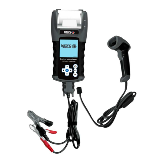
MBT2415 is our latest version of Battery Analyzer which test 12V systems (4 functions) and 24V systems on Starters
and Alternators (Normal and Smart). This tester revolutionized its display format and is the first in the world with fully
graphical display. The graphical display is simple; with step by step instructions enable the user to clearly understand
the operation. The symbols used are universal which solve language barrier.
The unit comes with an integrated printer so the graphical results can be printed immediately after each test. Its
memory stores up to 70 previous test results for later viewing. With its PC Link feature, allows the results to be
transferred and stored in the computer via an USB cable and PC Link software installed into the computer beforehand.
The Battery Analyzer operates on all 12V or 24V Batteries and is able to perform four tests namely:
1. Battery Test:
This Test is intended only on 12V batteries. The analyzer clips (red & black) have to be clamped onto the
battery terminals. When the analyzer detects the voltage present, the analyzer will automatically remind the user that
it can test only on 12V battery when connected to the 24V system.
Analyses the battery condition using microprocessor controlled testing methods without the need of fully
charging it before test.
The unit consumes very little current during testing hence the test can be repeated numerous times
without any worry of draining the battery and its results are highly accurate.
Extremely safe as it does not create any sparks during clamping and it takes less than 8 seconds to
obtain the full analyzed results of tested battery.
Temperature compensated end Results.
It is powered up from the testing 12V or 24V battery. No maintenance is required during its lifetime service.
2. Grounding Test:
Same as battery test, this test is also meant for 12V batteries only.
Advertisement
Table of Contents

Related Manuals for Matco Tools MBT2415


Summary of Contents for Matco Tools MBT2415
- Page 1 Introduction MBT2415 is our latest version of Battery Analyzer which test 12V systems (4 functions) and 24V systems on Starters and Alternators (Normal and Smart). This tester revolutionized its display format and is the first in the world with fully graphical display.
-
Page 2: Specifications
Analyses the condition of the electrical return circuit contacts resistance which were connected to the engine or chassis body from the battery terminal with results and recommendations display after test. 3. Starter Test: This Test can be performed on 12V and 24V Starters. Checks the cranking effectiveness of the battery to predict when the battery will fail to crank a vehicle basing on voltage profiles with results and recommendations display. -
Page 3: Safety Precautions
Safety precautions: When the engine is running, it produces carbon monoxide, a toxic and poisonous gas. Always operate the • vehicle in a well-ventilated area. Do not breathe exhaust gases – they are hazardous that can lead to death. To protect your eyes from propellant object such as caustic liquids, always wear safety eye protection. •... -
Page 4: Preparing For Test
Unfiltered [pulsating DC] electricity can damage expensive electronic components, e.g., emissions computer, radio, charging system, etc. Turn off all electrical switches and components; turn off the ignition before disconnecting the battery. For non-sealed batteries, check the electrolyte level. Make sure it is covering the plates and it is not frozen •... - Page 5 The date and time on the Analyzer were set in the factory during production. Due to the differences of the Time zone in your Country, you may need to set according to your local date & time and this can be done by doing the following steps: 1.
- Page 6 5. When the key in had finished, press key to save the entry and then press key to exit. Note: The information that has been keyed in will be shown in the result printout after test (see Fig.87). Switch ON / OFF Key Sound beep Whenever a key is press, there is a corresponding beep sound which can be heard as to indicate that a key has been pressed.
- Page 7 Testing on stand-alone Batteries: Clean the battery posts with a wire brush prior testing. For side post batteries, install stud adaptors. Do not use steel bolts for better results. 1. Clamp the Analyzer black clip to the battery negative terminal (-) and red clip to the battery positive terminal (+).
- Page 8 To key-in the particulars (e.g. VIN, vehicle registration numbers/ battery model/ testing date/ customer’s name/reference numbers/ etc. which can only be entered with a single choice having not more than 17 characters ), press key to scroll up the alphabet A,B,C ~Z and numbers1,2,3~0 while key to scroll down from Z,Y,X~A or 0,9,8~1 to select.
- Page 9 When this function is selected, it lets the user select and delete the result individually from the memory. Once entered, the display will show (Fig.18) as below which shows all the particulars that was key-in (type) during the test. Fig.18 Press key to scroll upwards and key to scroll downwards to select.
- Page 10 5. If the tester detected that the battery has surface charge it will prompt you to turn the ignition key to ON and switch on the headlights (Fig.21) to discharge the battery until it has reached to the next display that shows turn ignition OFF and headlights OFF (Fig.22) as display shown below and then press to continue.
- Page 11 9. If the rating is selected under JIS # (Japanese Industrial Standard) then you need to refer to the conversion chart provided separately with the Tester when purchased to convert to CCA ratings. Refer to the battery model (example: 80D26L or NX110-5L) on the Cold Cranking Amps (CCA), WET is 580 CCA and AGM is 630 CCA.
- Page 12 below: Fig.28 Here it let you to select the surrounding temperature that you are working with the battery. If the surrounding temperature is for example 15A C, then select and press key. Then the results will show on the LCD display (Fig.27). 15.
- Page 13 With the battery model in hand, refer to the Battery rating chart ( as seen in this example Fig.32 below) provided in separate copies with the Tester when purchased, to get values to be keyed in. Fig.32 Once the battery type [SLI (WET)] or [AGM] has been selected, it will proceed to the display as shown below (Fig.33): Fig.33 + Press...
-
Page 14: Interpretation Of Results
State of Charge (SOC) Rated CCA Measured CCA (Power Available) Ω Internal Resistance Fig.36 Life [Health] 23. To print out the results, just press key on the Analyzer, the printer will start printing. Interpretation of Results: The battery is in good condition. The battery is OK but need to recharge first in order to have the maximum performance. - Page 15 The battery capacity rated output is normally stated on the label for car batteries (either in CCA, EN, DIN, JIS, etc.). For batteries with model numbers, please refer the charts provided with the Analyzer. 4. Power available: 120 CCA It means that the battery tested has a capacity of 120 CCA power available. CCA ratings has been used here, therefore the tested result is in CCA and if other rating (DIN, SAE, JIS, IEC, CA, or EN) were selected, it will base on the respective rating to calculate and show the results in that selected rating.
- Page 16 This is an indication of the battery life expectancy [Health] in percentage. Explanation of the following terms used as shown on the LCD display: CCA (Cold Cranking Amps) – most commonly used Standard. • CCA is a rating used in the battery industry to rate a battery’s ability to start an engine in cold temperatures. This rating is the number of amperes that a new fully charged battery can delivery at 0 °...
- Page 17 To determine the condition of the tested Deep Cycle Batteries, refer the Volts reading – State of Charge (should not fall below 12.60V when fully charged for Lead Acid Batteries, 12.85V for Gel Batteries and 12.80V for AGM Batteries) and the Internal Resistance [Int. R] of the tested battery should not be more 15 m Ω...
-
Page 18: Starter Test
Starter Test: This test is only available in test and it actually checks the cranking effectiveness of the 12V or 24V battery system during starting and also the starter condition. 1. With engine OFF, place the vehicle transmission in NEUTRAL for Manual and PARK for Automatic then apply the hand brake. -
Page 19: Alternator Test
Fig. 45 Fig. 44 Note: 9.6 Volt is the voltage drop limit for 12V system whereas 19.2Volt is for 24V system. Voltage drop more than the limits mentioned are considered bad. 4. To print out the results, just press key on the Analyser, the printer will start printing. 5. - Page 20 Press key and the display will prompt you to select which type of Alternator (Smart or Normal) for testing (Fig. 47 below). Fig.47 Once selected, press key to continue and the display will show: (Fig.48). Start the engine if it is not running and keeps it running at idling speed.
- Page 21 Smart Alternator Charging: 12V System: No load - MAX voltage should not exceed 16.2V and MIN voltage should be more than 12.4V. Loaded - Should be more than 12.0V 24V System: No load - MAX voltage should not exceed 33.0V and MIN voltage should be more than 24.8V.
- Page 22 Fig. 54 Wait for the countdown from 10s to 0s. As soon as it reaches 0s, the results will automatically display as example shown below (Fig.55). Fig.55 9. If either minimum or maximum charging volts are not within the voltage range limits then it will display one of the screens as below (Fig.56 &...
-
Page 23: Grounding Test
10. Wait for the countdown from 10 to 0. As soon as it reaches 0, the results will automatically display as example shown below (Fig.60). Fig.60 11. If the ripple voltage is above 0.5V then it will display (Fig.61 ) as below: Fig.61 12. - Page 24 Note: To conduct Ground Resistance test on a 24V (12V x 2 Batteries) System, always look for the 12V Battery with its negative terminal connected to the vehicle chassis (see Fig. 63 above). Clamp the tester clips onto this battery terminals will be able to proceed with the Test. Start Testing 1.
- Page 25 8. When key is pressed, it will start analyzing and the display will changed to the screen (Fig.69) below: Fig.69 9. Once it has finished analyzing, it will prompt you with instructions (Fig. 70 & 71) stating that you have should unclamp the Black tester clip from the engine or chassis body and transfer to the battery negative [-] terminal within 15 seconds time limit if not the testing procedure has to be repeated again as the gathered data will be lost.
- Page 26 13. If the measured resistance reading has gone beyond the limits, then it will display the screen as follows (Fig. 75). Ω Fig.75 Note: The above indicates that the ground contact from the engine body to the battery is bad. Check for rusted or corroded point of contacts.
- Page 27 2. Select View Test Report from memory by scrolling with key to . See display below (Fig.79): Fig.79 3. Once key is pressed, the display will show as follows (Fig. 80): Fig.80 Select the particulars that you had keyed in earlier from the list by scrolling the highlighted bar up or down when pressing key.
- Page 28 Fig.87 Note: To printout on normal computer printer, it has to be connected to the PC with the Analyser software installed. (See Print Results from PC Printer – Page 34). To exit the program, pressing the key at any moment will exit and return back to the main menu screen (Fig.79).
- Page 29 As instructed, click [Next>] tab the program will continue to install the driver on the computer. Once it had finished, it will prompt you as shown below. Click [Finish] tab to complete the installation. Step 3. Next open this folder again: Look for the program icon: Then double click to open the program.
- Page 30 A few seconds later, the display will show as below that the installation has been completed and click “OK” tab to exit. Once the software has been installed, the icon will appear on the desktop. Step 4. Now plug the Analyzer into any one of the PC USB port and try to link up the Analyser with the PC by the following procedures: 1.
- Page 31 Click Header & Footer here to put your Company name and address. 1. To confirm whether there is communication; click on [Transfer Data from Analyser] tab and the Test Result will appear. See example below. You can type in the particulars here.
-
Page 32: Printing Results From Pc Printer
If the above fails again, then try plugging the Analyzer to the PC’s another USB port and repeating Step 4 and 5 again. Printing Results from PC Printer: While on this page, if you wish to print out the results, make sure that your printer is connected to the computer. Click on tab and a text box will appear. - Page 33 On [Page Layout], left click on sign (see Fig. A) to show Page Setup dialogue box as shown (Fig. B) below. Then select [Paper] tab and browse [paper size] drop down menu for A4 click on it (Fig. C). Click [OK] to apply and confirm. Fig.
-
Page 34: Warranty Information
1. Press and hold keys together, a few seconds later the display will change to (Fig. 96) as shown below and that completes the process. Fig.96 Warning: Performing the above procedures will erase off all the records from the tester. Disclaimer All information, illustrations, and specifications contained in this user manual are based on the latest information available at the time of printing. - Page 35 Physical damage to the product surface including scratches, cracks or other damage to the display • screen or other externally exposed parts. Limitations of Warranty Other than the foregoing limited warranty, the manufacturer does not make any other warranty or condition of any kind, whether express or implied.
Need help?
Do you have a question about the MBT2415 and is the answer not in the manual?
Questions and answers