
Subscribe to Our Youtube Channel
Related Manuals for Universal Remote MRF-350


Summary of Contents for Universal Remote MRF-350
- Page 1 MRF-350 Installation Manual Optimizing Narrow Band Reception with the RFX-250 and MSC System Remotes ™ COMPLETE COMPLETE CONTROL Universal Remote Control ®...
- Page 2 The information in this manual is copyright protected. No part of this manual may be copied or reproduced in any form without prior written consent from Universal Remote Control, Inc. UNIVERSAL REMOTE CONTROL, INC. SHALL NOT BE LIABLE FOR OPERATIONAL,TECHNI- CAL OR EDITORIAL ERRORS/OMISSIONS MADE IN THIS MANUAL.
-
Page 3: Table Of Contents
Introduction Features and Benefits Parts Guide Optimizing Range and Reliability Connecting IR and Setting Output Levels Front Blaster Overload Disabling the Front Blaster - Step by Step via PC Controlling An Array of Identical Components or Zones Identical Components/Zones - Step by Step via PC Programming For Multiple Equipment Locations Frequently Asked Questions Warranty... -
Page 4: Introduction
MRF-350 B Introduction The MRF-350 base station is an “addressable” base station like the MRF-300. RF Addressing gives you the ability to control as many as 90 identical compo- nents throughout a house. However, the MRF-350 is equipped with the Narrow Band RF reception, so is only compatible with MSC System remotes. -
Page 5: Features And Benefits
Each MRF-350 has six “addressable” IR Line Outputs. For example, you can con- trol up to six identical TV’s with one MRF-350 or route volume commands for a specific zone to a particular zone IR input on a multi-zone preamp. If you have... -
Page 6: Optimizing Range And Reliability
RF Interference (particularly devices with high speed microprocessors or hard drives). 2. Check that the address wheel on the bottom of the MRF-350 is set to ID#0 (the interference “sniffing” position). Slide off the mounting plate to reveal the RF ID# rotary switch. Check that the arrow pointer in the center of the wheel is pointed to 0, the default “interence sniffing”... - Page 7 RF LED. If it is glowing or flickering you must relocate the RFX-250 to a location where the LED doesn’t flicker. 6. Observe the STATUS LED of the MRF-350. It is a little more sensitive than the RFX-250. If you see any flickering of this LED, move the RFX- 250 to a new location.
- Page 8 VALID RF ID#. Keep in mind that zero (0) is not a valid RF ID#. Watch the STATUS LED on MRF-350 - it should light every time you press a button on the remote. This will tell you that the signal was received and understood.
-
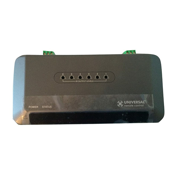
Page 9: Connecting Ir And Setting Output Levels
Operation should be identical. RF is not slower. If operation is inconsistent or sluggish, LOWER the IR line output. If you still have sluggish operation, check that the remote control is set to a particular LINE OUT, rather than ALL.When IR commands are sent to all the flashers in a cabinet, you can have difficulty adjusting the IR Output. -
Page 10: Front Blaster Overload
Disable the Front Blaster. This will limit the number of components your MRF-350 can control to six. If you have more than six components you can purchase an additional MRF-350. -
Page 11: Controlling An Array Of Identical Components Or Zones
DATA input and the copper colored conductor to the GROUND connector of the component’s rear panel IR input. Then adjust the line output of the MRF-350 for the best performance if needed. Identical Components/Zones - Step by Step via PC Step 1 - Create a Device for Each Component/Zone in the MX Editor Software. - Page 12 MRF-350 B TATION Step 3 - Copy The Programmed Device In tree view, right click on the device you programmed. From the context menu that appears, select COPY. Step 4 - Paste The Programmed Device In tree view, right click on the first device that is NOT PROGRAMMED.
- Page 13 The RF Setup window enables you to adjust which Flashers output by the remote control for each device individually, by clicking on the intersection of a row and a column and then selecting 1-6 from the seven options shown in the pull down list box.
-
Page 14: Programming For Multiple Equipment Locations
CELL and selecting the ID# you want from the pull down list. Each LOCATION should have a unique ID#. It is ok to install multiple MRF-350’s in one location. Step 4 - Save and Download to your remote. TATION... -
Page 15: Frequently Asked Questions
ID# from 1-9 or A-F must be set on both the remote control and the bottom of the MRF-350, second, check that the flasher level is set to the minimum necessary, third, check that the emitter is facing the component, fourth, make sure the RFX-250 is cor-... -
Page 16: Information To The User
Such modifications could void the user's authority to operate the equipment. COMPLETE COMPLETE CONTROL 500 Mamaroneck Avenue, Harrison, NY 10528 Phone: (914) 835-4484 Fax: (914) 835-4532 www.universalremote.com Warning Universal Remote Control ™ ®...
Need help?
Do you have a question about the MRF-350 and is the answer not in the manual?
Questions and answers