Unitech MS860 Bluetooth User Manual
Wifi bar code scanner
Hide thumbs
Also See for MS860 Bluetooth:
- Quick start manual (4 pages) ,
- Specifications (2 pages) ,
- User manual (56 pages)
Table of Contents
Advertisement
Quick Links
Advertisement
Chapters
Table of Contents

Related Manuals for Unitech MS860 Bluetooth


Summary of Contents for Unitech MS860 Bluetooth
-
Page 1: Bar Code
MS860 WiFi Bar Code Scanner REV.C... -
Page 2: Table Of Contents
Bar Codes ....17 Install Virtual COM Scanner Configuration ....31 Programming with Scanner Configuration Manager ..31 Start it Up . -
Page 3: Introduction
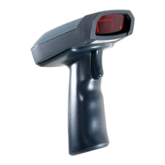
INTRODUCTION The MS860 WiFi laser bar code scanner is one of the newest members of Unitech’s MS series. The MS860 incorporates the latest WiFi technology, making it ideal for real-time bar code data collection in warehouse, loading dock, inventory, back office, document tracking, retail environments - anywhere cables would restrict movement or limit access. -
Page 4: Introduction
Double click one of the VCOM icons and the Virtual Com utility screen will appear. Once the scanner is connected to the WLAN, the flashing green LED on Press the “CONFIG” button. Enter an IP address and (virtual) com the scanner turn into steady green. -
Page 5: Enter Group 4
AP, between 5 to 8 scanned data records may not have been sent to the network, even though the scanner gives a “good read” signal after each of them. -
Page 6: Scanner And Accessories
MS860-W8E: MS860 WiFi laser scanner w/UP plug Scan: 400479: Unitech MS860 WiFi Scanner user guide CD Enter Group 7 400480: Unitech MS860 WiFi Scanner quick start guide sheet *Scanner Configuration Manager: Windows based software providing a user-friendly interface for easier scanner configuration. Exit After “ACK”... -
Page 7: Scanner Parts
Upon exiting configuration mode, the scanner will emit one high tone LED will stop flashing. beep, and the scanner’s LED will stop flashing. 2. The scanner is powered on but not yet connected to the WLAN or the Green LED remains ON connection to the WLAN is broken. - Page 8 If the Access Point is powered off, this means the communication between the scanner and the Access Point is lost. You will also hear a continuous high-low beep from the scanner when you scan bar codes.
-
Page 9: Cradle Parts
The red LED indicates the scanner battery is charging. Battery Charging Status LED remains Green The LED changes to green when scanner battery charging is complete. Please Note: The MS086 Cradle has an interface port (to the left of the power plug) and a communication LED next to the two other LEDs. -
Page 10: Charging The Scanner
LED changes from red to green. Manufacturer’s Suggestion: If the scanner is not to be used for a long period of time, it is recom- mended that you turn off the battery power of the scanner. Use an... -
Page 11: Network Settings
(AP), which then communicates with the host computer. The host computer uses the VCOM utility to convert the WiFi signal to a Virtual Com Port (RS232) signal, which the host computer recognizes as one of the standard scanner interfaces. Item IP Address... -
Page 12: Modifying The Wifi Settings
10. Scanner Configuration Manager (SCM) is a proven and powerful utility for scanner configuration. Easy to use, it is probably the most straightforward method of modifying your MS860’s wireless settings. Because of the wireless communication between the MS860 and the host computer, SCM settings cannot be directly downloaded to the MS860. -
Page 13: Glossary
NETWORK SETTINGS GLOSSARY IP Address IP Address (short for Internet Protocol) is simply four numbers (like 192.168.1.250) separated by periods that is used to identify a particular device within a network, just as an employee number is used to identify an individual person within a com- pany. - Page 14 This information is not strictly necessary, but might be useful in order to maintain order over several MS860 units. Alias Alias is merely a name for the scanner that would be more easily recognizable than an IP Address. For instance: “Fred’s MS860”, “S103”, or “Warehouse-23”.
- Page 15 NETWORK SETTINGS NETWORK SETTINGS There are two methods to configure your scanner to its IP settings (obtained from your Network Administrator) - via Scanner Configuration Manager (SCM) and via manual bar code scanning. SCM has the advantage in that it’s quick and easy, and works for most situations.
- Page 16 NETWORK SETTINGS Step 3: Fill in the SSID name of the Access Point (AP). Click “Next”. Step 4: Select wireless network type. Step 5: Select “Yes” for DHCP on, “No” for DHCP off. Step 6: If DHCP “Off” is selected, fill in the IP Address, Subnet Mask, and Gate- way.
- Page 17 Click “Next” when finished. Step 11: Setup is complete. Step 12: Select an appropriate printer to produce a setup sheet containing bar codes. Use your MS860 scanner to scan the barcodes on the sheet sequentially to configure the scanner. MS860 WiFi Manual...
- Page 18 21 to 24. Some Access Points may not be able to re-connect to the MS860 after it’s been out of range. In this case the scanner will need to be powered off and powered on again, and the VCOM communi- cation must be re-started.
- Page 19 IP Subnet Mask Gateway IP Address Authentication Type Use the TCP/IP barcode chart on page 81 and the ASCII Chart on pages 83 to 86 to configure your scanner to your own network settings, as the example below: SSID: MySSID IP: 192.168.1.100 Mask: 255.255.255.0...
- Page 20 NETWORK SETTINGS General Command List: MODE <B(SS) / A(d-hoc) / P(seudo / BSS)>, Set network mode SSID <SSID>, Set SSID CHAN <1 - 14>, Set channel PSMODE <1 / 0>, PS mode ON/OFF <1 / 0>, WEP ON/OFF DEFAULT Restore configuration to factory default SAVE Save configuration to flash EXIT...
- Page 21 NETWORK SETTINGS 7. WEP Turn WEP on or off Example: WEP Space 1 CR (turn on WEP) Example: WEP Space 0 CR (turn off WEP) 8. WKID Set which WEP key that you want to use, of which you have four. Example: WKID Space 1 CR (use WEP key number 1) Example: WKID Space 2 CR (use WEP key number 2) Example: WKID, Space 3 CR (use WEP key number 3)
- Page 22 Example: EXIT CR IMPORTANT: Once you have completed the network configuration for the scanner, VCOM will be required to configure the virtual com port, which means the VCOM utility must run in the background. This is detailed on pages 21 to 24.
-
Page 23: Install Virtual Com
NETWORK SETTINGS After you have configured your MS860’s IP settings, follow the steps below and on the next page to install and start VCOM. VCOM estab- lishes a “virtual com port” on your host computer that coordinates with your MS860’s IP address. INSTALLING VIRTUAL COM Step 1: Install VCOM utility... - Page 24 NETWORK SETTINGS Step 4: Click “Next” and confirm information. The installation procedure will start automatically. Step 5: Click “Finish” to complete the installation process. MS860 WiFi Manual...
- Page 25 NETWORK SETTINGS START VIRTUAL COM: Step 1: Start the Virtual Com utility from the Icon Tray. Click the “Config” button. Step 2: Set the virtual com port associated with the corresponding IP address to your wireless module. Click the “Add” button to add a VCOM = IP pair to the list on the right.
- Page 26 Some Access Points may not be able to re-connect to the MS860 after it’s been out of range. In this case the scanner will need to be powered off and power on again, and the VCOM communica- tion must be re-started.
-
Page 27: Scanner Configuration
Access Point to communicate data through. If this doesn’t happen 2. Double click DevMgrU. automatically, then refer to the Troubleshooting section (page 76). 3. Once the scanner is connected to the access point, the scanner should be searched and found by the monitor.exe. (Or you can click VCOM “Re-scan”... - Page 28 NETWORK SETTINGS GLOSSARY IP Address IP Address (short for Internet Protocol) is simply four numbers (like 192.168.1.250) separated by periods that is used to identify a particular device within a network, just as an employee number is used to identify an individual person within a com- pany.
- Page 29 This information is not strictly necessary, but might be useful in order to maintain order over several MS860 units. Alias Alias is merely a name for the scanner that would be more easily recognizable than an IP Address. For instance: “Fred’s 3. “Advanced” is enabled. You can click “Advanced” button to MS860”, “S103”, or “Warehouse-23”.
- Page 30 NETWORK SETTINGS 4. Keep the default settings of the server port and server IP. NETWORK SETTINGS There are two methods to configure your scanner to its IP settings Note: (obtained from your Network Administrator) - via Scanner Configuration Manager (SCM) and via manual bar code scanning. SCM has the 1.
- Page 31 Step 3: Fill in the SSID name of the Access Point (AP). Click “Next”. 1. After you have set the network configuration for your scanner and set the virtual com port, you are ready to scan data and transmit them to your server thru the WiFi.
- Page 32 Click “Next” when finished. Step 11: Setup is complete. Step 12: Select an appropriate printer to produce a setup sheet containing bar codes. Use your MS860 scanner to scan the barcodes on the sheet sequentially to configure the scanner. MS860 WiFi Manual...
-
Page 33: Start It Up
The other two icons are non-functional in the MS860 WiFi because of its wireless nature, but they represent download settings to scanner and upload settings to computer for other scanner models. Downloading to the MS860 can otherwise be accomplished by clicking the Print icon (see next page) and scanning the resulting configuration bar codes. - Page 34 For information on data editing, see page 78. Click this icon to print a series of bar codes that you can scan in order to configure your scanner to the current SCM settings. If you can produce PDF files via Acrobat, your SCM configura- tion can be sent via e-mail to remote locations where they can be scanned from a printed PDF file (without having to run SCM).
-
Page 35: Try It
SCANNER CONFIGURATION MANAGER Try It! Click the SCM Icon, if you haven’t already done so. Two work areas appear with a row of icons along the top. Click the icon furthest to the left (new file). The screen to the right appears. -
Page 36: Settings
Default is “1 ms”. Keyboard Wedge Your Unitech reader contains a built-in data decoder that translates raw bar code input into Keyboard Scan Code, or ASCII Code in the case of RS232 interface readers, with the result that scanned data exits the reader as if you had typed the text. - Page 37 F1 label will display a “Help” pop-up box, F3 will display a “Find” pop-up box, etc. If No is selected, the scanned function codes will output special character strings defined by Unitech for non-print character output. Default is “Yes”. Caps-Lock The Caps-Lock function determines how the Caps Lock key controls the case of alphabetical characters.
-
Page 38: Rs232
SCANNER CONFIGURATION MANAGER Step 5: Select DHCP on or off. Click “Yes” for DHCP on and click RS232 “No” for DHCP off. The RS232 input characteristics of the MS860 can be modified accord- ing to the following nine parameters: Baud Rate Baud Rate (bits per second) refers to the speed of the data from the MS860. -
Page 39: Time Out
SCANNER CONFIGURATION MANAGER Step 7: Select “Yes” or “No” if your wireless network using WEP RS232, continued encryption for data security or not, click “Next”. BCC Character Block Check Character. An error checking character added for data integrity. Default is “No”. -
Page 40: Scanner Port
Step 9: Select “YES” for using power saving mode. Click “Next”. Scanner Port Scanner Port parameters refer to scanner functions (such as Double Verification, Scanning Mode, etc.) and some simple data editing features. For more powerful data editing, refer to the Data Editing section starting on page 44. - Page 41 Default is “No”. Step 12: Click “Finish” will allow you to print out a setup sheet, please scan the barcode labels on it to configure your scanner. Double Verification Double Verification enables the MS860 to verify the accuracy of the output by outputting only after a specified number (from 0 to 7) of identical results.
-
Page 42: Beeps And Delays
Default is “1 ms”. Keyboard Wedge Your Unitech reader contains a built-in data decoder that translates raw bar code input into Keyboard Scan Code, or ASCII Code in the case of RS232 interface readers, with the result that scanned data exits the reader as if you had typed the text. - Page 43 F1 label will display a “Help” pop-up box, F3 will display a “Find” pop-up box, etc. If No is selected, the scanned function codes will output special character strings defined by Unitech for non-print character output. Default is “Yes”. Caps-Lock The Caps-Lock function determines how the Caps Lock key controls the case of alphabetical characters.
- Page 44 SCANNER CONFIGURATION MANAGER RS232 The RS232 input characteristics of the MS860 can be modified accord- ing to the following nine parameters: Baud Rate Baud Rate (bits per second) refers to the speed of the data from the MS860. Normally, the baud rate of the host RS232 port should match that of the input device.
- Page 45 SCANNER CONFIGURATION MANAGER RS232, continued BCC Character Block Check Character. An error checking character added for data integrity. Default is “No”. Time Out The ACK/NAK function (see previous page) can be given a limited time (from 1 to 10 seconds) or an unlimited time to operate.
- Page 46 SCANNER CONFIGURATION MANAGER Scanner Port Scanner Port parameters refer to scanner functions (such as Double Verification, Scanning Mode, etc.) and some simple data editing features. For more powerful data editing, refer to the Data Editing section starting on page 57.
- Page 47 SCANNER CONFIGURATION MANAGER Scanner Port, continued Use Code ID The Code ID function can be used to identify the type of bar code that is being scanned by inserting an identifying letter (refer to the chart at right) at the begin- ning of the bar code input.
-
Page 48: Scanning Mode
Scanning can occur in seven different ways: Trigger scan causes the scanner light to remain on as long as the trigger is depressed, whether the bar code is recognized or not. Flashing causes the scanner to flash continuously after the trigger is briefly pressed until it detects a bar code and outputs the data. - Page 49 Scanner Port, continued Aim Function for Long Range Engine The Aim function causes a laser scanner to output a “pin-point” aiming aid for a specified period of time (see below) to enable a user to more easily scan distant bar code labels.
-
Page 50: Bar Code Symbologies
Following are the bar code symbologies and their modifiable parameters. Code 39 Enabled toggles the ability for the scanner to read Code 39 on or off. Default is “Yes”. Code ID (Standard) is a user-definable identification letter for Standard Code 39, which is referred to in the “Use Code ID”... -
Page 51: Interleaved 2 Of 5
Bar Code Symbologies, continued Interleaved 2 of 5 Enabled toggles the ability for the scanner to read I 2 of 5 on or off. Default is “Yes”. Code ID is a user-definable identification letter for I 2 of 5, which is referred to in the “Use Code ID”... - Page 52 SCANNER CONFIGURATION MANAGER Bar Code Symbologies, continued Standard 2 of 5 / Toshiba Code (China Postal Code) Enabled toggles the ability for the scanner to read S 2 of 5 / Toshiba Code on or off. Default is “No”. S25 Code ID is a user-definable identification letter for S 2 of 5, which is referred to in the “Use Code ID”...
-
Page 53: Code 128
SCANNER CONFIGURATION MANAGER Bar Code Symbologies, continued Code 32 Enabled toggles the ability for the scanner to read Code 32 on or off. Default is “No”. Code ID is a user-definable identification letter for Code 32, which is referred to in the “Use Code ID” function on page 45. - Page 54 Maximum Length defines the maximum length the user will accept for a valid bar code. Default is “64”. Code 93 Enabled toggles the ability for the scanner to read Code 93 on or off. Default is “Yes”. Code ID is a user-definable identification letter for Code 93, which is referred to in the “Use Code ID”...
- Page 55 SCANNER CONFIGURATION MANAGER Bar Code Symbologies, continued Codabar Enabled toggles the ability for the scanner to read Codabar on or off. Default is “Yes”. Code ID is a user-definable identification letter for Codabar, which is referred to in the “Use Code ID” function on page 45.
- Page 56 SCANNER CONFIGURATION MANAGER Bar Code Symbologies, continued UPC-E Enabled toggles the ability for the scanner to read UPC-E on or off. Default is “Yes”. Code ID is a user-definable identification letter for UPC-E, which is referred to in the “Use Code ID” function on page 45.
- Page 57 Send Check Digit toggles sending or not sending a check digit. Default is “Send”. Code 11 Enabled toggles the ability for the scanner to read Code 11 on or off. Default is “Yes”. Code ID is a user-definable identification letter for Code 11, which is referred to in the “Use Code ID”...
- Page 58 Default is “No”. Label Code IV and V Enabled toggles the ability for the scanner to read Label Code IV and V on or off. Default is “No”. Code ID is a user-definable identification letter for Label Code IV and V, which is referred to in the “Use Code ID”...
-
Page 59: Data Editing
SCANNER CONFIGURATION MANAGER Data Editing Data Editing is a powerful function that can give you tremendous control over how data is exported from the MS860. After clicking on “Data Editing” the data editing icons become active. Click on the icon with the blue circle and white plus sign. - Page 60 SCANNER CONFIGURATION MANAGER Data Editing, continued Note: Even if the original bar code data is not modified, if additional charac- ters are to be added (see “Add New” below) the original Start Param- eter must be defined as From Position “1” and the End Parameter defined as “All Remaining”, otherwise, none of the original data will be...
- Page 61 If the scanned bar code does not satisfy the requirements of the Qualifier(s) (see page 57), then no data is output. Practically speaking, the scanner has been set up to scan only bar codes that are defined by the Qualifier(s).
-
Page 62: Introduction
Introduction In addition to the Scanner Configuration Manager software, your MS860 scanner can also be configured via bar code input by scanning in the bar codes on the following pages. The concept (for Groups 2 through 8) is fairly simple: Parameters are associated together into groups. -
Page 63: Quick Setup Bar Codes
PROGRAMMING VIA SCANNER INPUT Quick Setup Bar Codes Device Type AT Keyboard Wedge Wand Emulation PS/2 Keyboard Wedge IBM Terminal Serial Interface Macintosh Keyboardless Wedge Terminal Wedge Inter-Character Delay 1 millisecond 20 milliseconds Code ID Scan Code U.S. Alt Key... -
Page 64: Factory Default
PROGRAMMING VIA SCANNER INPUT Quick Setup Bar Codes, continued EAN-8 Default Cut Leading Digit Cut Check Digit EAN-13 Default Cut Leading Digit Cut Check Digit ISBN Conversion Display Version Display Version MS860 WiFi Manual Menu Setup Enable / Disable Supplemental... -
Page 65: Beeps And Delays
PROGRAMMING VIA SCANNER INPUT Beeps and Delays Enter Group 2 Beep Tone: (see page 40) 0 - None 1 - Low 2 - Medium 3 - High 4 - Low to High 5 - High to Low Interblock Delay: (see page 40) -
Page 66: Keyboard Interface
PROGRAMMING VIA SCANNER INPUT Keyboard Interface Enter Group 3 MS860 WiFi Manual Function Code: (see page 41) 0 - Off 1 - On Caps-Lock: (see page 41) 0 - Auto Trace (PC/AT) 1 - Lower Case 2 - Upper Case... -
Page 67: Rs232
PROGRAMMING VIA SCANNER INPUT RS232 Enter Group 4 Baud Rate: (see page 42) 0 - 300 4 - 4800 1 - 600 5 - 9600 2 - 1200 6 - 19200 3 - 2400 7 - 38400 Parity: (see page 42) - Page 68 PROGRAMMING VIA SCANNER INPUT RS232, continued MS860 WiFi Manual BCC Character: (for serial wedge) (see page 43) 0 - Off 1 - On Time Out: (for serial wedge) (see page 43) 0 - 1 second 1 - 3 seconds 2 - 10 seconds...
-
Page 69: Scanner Port
PROGRAMMING VIA SCANNER INPUT Scanner Port Enter Group 5 Terminator: (see page 44) 0 - Enter 1 - Return (on keypad) 2 - Field Exit or Right Ctrl 3 - None Code ID: (see page 45) 0 - Disable 1 - Enable Note: This setting does not affect EAN 128 Code ID. - Page 70 PROGRAMMING VIA SCANNER INPUT Scanner Port, continued MS860 WiFi Manual Double Verification: (see page 45) 0 - Off 1 ~ 7 - On (verify 1 to 7 times) Scanning Mode: (see page 46) 0 - Trigger 1 - Flashing 2 - Multiscan...
- Page 71 PROGRAMMING VIA SCANNER INPUT Scanner Port, continued A Preamble can be inserted before, or a Postamble can be inserted after the scanned bar code data (inserting a Tab, for instance). To insert a postamble, scan the “Postamble” (OO) bar code, scan your selected postamble from the Function Code (page 82) or ASCII Code (pages 83 to 86) Charts, and then scan the “Postamble”...
-
Page 72: Symbologies
PROGRAMMING VIA SCANNER INPUT Symbologies - Group 6 Enter Group 6 MS860 WiFi Manual Code 39: (see page 48) 0/1 - Disable / Enable 2/3 - Full ASCII / Standard 4 - Check Digit Calculate and Send 5 - Check Digit Calculate, Not Send... -
Page 73: 0/1 - Disable / Enable 2/3 - Fix Length On / Off F2
PROGRAMMING VIA SCANNER INPUT Symbologies - Group 6, continued Standard 2 of 5 / China Postal Code / Toshiba Code: (see page 50) 0/1 - Disable / Enable 2/3 - Fix Length On / Off (by first three reads) 4 - Check Digit Calculate and Send... - Page 74 PROGRAMMING VIA SCANNER INPUT Symbologies - Group 6, continued MS860 WiFi Manual Define the EAN 128 Fields Separator: Scan from the ASCII Code Chart (pages 83 to 86) to define a new fields separator. Define a Separator for Double Labels:...
- Page 75 PROGRAMMING VIA SCANNER INPUT Symbologies - Group 7 Enter Group 7 Code 128: (see page 51) 0/1 - Disable / Enable 1 ~ 64 - Min. Length 1 / Max. Length 64 (see page 72 for Min./Max. Length procedure) MSI / Plessey Code:...
- Page 76 PROGRAMMING VIA SCANNER INPUT Symbologies - Group 7, continued MS860 WiFi Manual Code 11 (Special): (see page 55) 0/1 - Disable / Enable 2/3 - One / Two Check Digit 4/5 - Check Send / No Send 1 ~ 48 - Min. Length 1 / Max. Length 48 (see next page for Min./Max.
- Page 77 PROGRAMMING VIA SCANNER INPUT Symbologies - Group 7, continued Define Minimum and Maximum Length: To define minimum or maximum acceptable bar code data length, after scanning the parameter code (G1 to G5), scan the “MM” or “NN” bar codes below, scan the number(s) to the left, and then scan the “MM”...
- Page 78 PROGRAMMING VIA SCANNER INPUT Symbologies - Group 8 Enter Group 8 MS860 WiFi Manual UPC-A: (see page 53) 0/1 - Disable / Enable 2/3 - Leading Digit Send / No Send 4/5 - Check Digit Send / No Send UPC-E:...
- Page 79 PROGRAMMING VIA SCANNER INPUT Symbologies - Group 8, continued Supplement Code: (see page 56) 0/1 - Two Supplement Code Off / On 2/3 - Five Supplement Code Off / On 4 - Transmit if Supplement Code is present (even if Two/Five Supplement Code is on)
-
Page 80: Data Editing
Modifiers modify the data output according to pre-set rules by either removing specified parts of the data or adding user-defined data. When programming the scanner, qualifiers must precede modifiers. Each programming parameter is output according to the following patterns: Qualifiers: Input ID - Specific bar code symbologies can be selected for special treatment. - Page 81 PROGRAMMING VIA SCANNER INPUT Data Editing, continued Note: Once a Qualifier is specified, other bar codes that do not meet the requirements of the Qualifier will be disregarded. If you would like bar codes not specified by the Qualifier to output normally, simply add another qualifier that specifies all bar codes (19), starting at position 1, and outputting all remaining (#).
- Page 82 PROGRAMMING VIA SCANNER INPUT Data Editing, continued Enter Group 9 Code Type: 0- Code 39 Full 1 - Code 39 Std. 2 - EAN-13 3 - UPC-A 4 - EAN-8 5 - UPC-E 6 - I 2 of 5 7 - Codabar...
-
Page 83: Tcp/Ip
PROGRAMMING VIA SCANNER INPUT TCP/IP Enter Group 10 Before configuring TCP/IP, power off the scanner, and then scan “Enter Group 10” within the first 5 seconds after switching the scanner back on. . (Period) For TCP/IP instructions, see page 17. -
Page 84: Function Codes
PROGRAMMING VIA SCANNER INPUT Function Codes for PC (Characters in parentheses represent Code 39 bar code printing.) F1 (%VA) F2 (%VB) F3 (%VC) F4 (%VD) F5 (%VE) F6 (%VF) F7 (%VG) F8 (%VH) F9 (%VI) F10 (%VJ) F11 (%VK) MS860 WiFi Manual... -
Page 85: Ascii Chart
PROGRAMMING VIA SCANNER INPUT ASCII Chart (Characters in parentheses represent Extended Code 39.) SOH ($A) STX ($B) ETX ($C) EOT ($D) ENQ ($E) ACK ($F) BEL ($G) BS ($H) HT ($I) LF ($J) VT ($K) FF ($L) CR ($M) SO ($N) - Page 86 PROGRAMMING VIA SCANNER INPUT ASCII Chart, continued (Characters in parentheses represent Extended Code 39.) < (%G) = (%H) > (%I) ? (%J) [ (%K) \ (%L) ] (%M) ^ (%N) _ (%O) { (%P) | (%Q) MS860 WiFi Manual } (%R)
- Page 87 PROGRAMMING VIA SCANNER INPUT ASCII Chart, continued (Characters in parentheses represent Extended Code 39.) 0 (/P) 1 (/Q) 2 (/R) 3 (/S) 4 (/T) 5 (/U) 6 (/V) 7 (/W) 8 (/X) 9 (/Y) : (/Z) MS860 WiFi Manual...
- Page 88 PROGRAMMING VIA SCANNER INPUT ASCII Chart, continued (Characters in parentheses represent Extended Code 39.) a (+A) b (+B) c (+C) d (+D) e (+E) f (+F) MS860 WiFi Manual g (+G) h (+H) i (+I) j (+J) k (+K) l (+L)
- Page 89 V, MSI Code, Plessey Code, Standard 2 of 5, UPC-A, UPC-E Trigger, Flash, Multiscan, and One Press-One Scan PS/2, RS232, TCP/IP Via Scanner Configuration Manager software (downloadable from www.ute.com) or bar code setup menus in manual Almost unlimited Lithium-ion 1900mAh - charged via cradle Fully charged (4.2V) in 4 to 5 hours...
- Page 90 SPECIFICATIONS MECHANICAL Scanner Dimensions: Cradle Dimensions: Scanner Weight: Cradle Weight: ENVIRONMENTAL Temperature: Humidity: Mechanical Shock: ESD Protection: COMMUNICATION Radio Frequency: Scalability: Range: WLAN Default Settings: RS232 Default Settings: MS860 WiFi Manual Length - 5” (126mm) Width = 3.25” (83mm) Height = 5.625” (143mm) Length - 8.125”...
-
Page 91: Troubleshooting
Caution: This procedure will erase special configurations that you would have created. Test the scanner on other ports. Unitech scanners are built to the highest standards, and a perceived scanner malfunction may actually be a malfunction in the host computer. -
Page 92: Problems And Solutions
Problems and Solutions Problem: Scanner doesn’t light up. If the scanner does not emit a light when the trigger is pressed, make sure the scanner is switched on (see page 5), and/or that the battery is charged (see page 8). - Page 93 TROUBLESHOOTING Problems and Solutions, continued Problem: No output from scanner. Try the scanner on other com ports (if available) or other computers to see if it’s a hardware problem. If the scanner appears to scan (emits a light and beeps), but does not output data, try scanning into a HyperTerminal session to see if it’s an application problem.
- Page 94 TROUBLESHOOTING Problems and Solutions, continued Step 5: Close VCOM and test the MS860’s network MS860 WiFi Manual connection as follows: Open a DOS session (Start / Run / type “cmd”). Type “ping ##.##.##.##” (replacing # symbols with your MS860’s actual IP address). The results should be similar to that below: If no packets are found, try a few more times.
-
Page 95: Bar Code Test Chart
BAR CODE TEST CHART A22357000599876B Codabar OQB2M5 Code 32 UNITECHE Code 39 with Check Digit Unitech128 Code 128 3 4 5 3 8 0 1 2 EAN-8 123456789-0 Code 11 WEDGE Code 39 123ABC Code 93 0123456 Delta Code MS860 WiFi Manual... - Page 96 BAR CODE TEST CHAR 0 4 5 2 1 4 8 3 4 1 2 3 EAN-13 (01)054123456789(01)659344 EAN 128 0987654321 Interleaved 2 of 5 0 0 2 7 0 7 8 9 5 7 6 3 0 2 3 9 8 957-630-239-0 ISBN 10017...
Need help?
Do you have a question about the MS860 Bluetooth and is the answer not in the manual?
Questions and answers