Advertisement
Advertisement
Table of Contents

Related Manuals for AGCO Perkins 1100 Series


Summary of Contents for AGCO Perkins 1100 Series
- Page 1 ENGINE SERVICE MANUAL Perkins® 1100 Series 6-Cylinder Diesel Engine R1310...
-
Page 2: To Our Customer
This equipment is covered by a written warranty which will be provided to you by your AGCO® Dealer at time of purchase. ® AGCO reserves the right to make changes or add improvements to its products at any time without incurring any obligation to make such changes to products manufactured previously. - Page 3 This publication is written in Perkins Approved Clear English Chapters 1 General information 2 Specifications 3 Cylinder head assembly 4 Piston and connecting rod assemblies 5 Crankshaft assembly 6 Timing case and drive assembly 7 Cylinder block assembly 8 Engine timing 9 Aspiration system 10 Lubrication system 11 Fuel system...
- Page 4 1100 Series model VK Contents 1 General information Introduction ..................1 Engine views (side mounted turbo) ...
-
Page 5: Cylinder Head Assembly
1100 Series model VK 3 Cylinder head assembly General description ................41 Rocker cover Operation 3-1 To remove and fit the rocker cover ........... 42 Rocker assembly Operation 3-2 To remove and to fit ... - Page 6 1100 Series model VK 4 Piston and connecting rod assemblies General description ................73 Big end bearing Operation 4-1 To remove ..
- Page 7 1100 Series model VK Rear end oil seal assembly Operation 5-4 To remove and to fit the rear end oil seal assembly ......93 Operation 5-5 To remove and to fit a crankshaft palm wear sleeve ....... 97 Thrust washers Operation 5-6 To check crankshaft end-float .
- Page 8 1100 Series model VK Fuel pump gear .................. 121 Operation 6-10 To remove ..............121 Operation 6-11 To fit .
- Page 9 1100 Series model VK 9 Aspiration system General description ................157 Turbocharger Operation 9-1 To remove ............... 159 Operation 9-2 To fit ...
- Page 10 1100 Series model VK Sump Operation 10-6 To remove ..............179 Operation 10-7 To fit an aluminium sump ............ 180 Operation 10-8 To fit a cast iron sump ..
- Page 11 1100 Series model VK Fuel lift pump Operation 11-4 To remove and to fit ............205 Operation 11-5 To dismantle ..............206 Operation 11-6 To assemble .
- Page 12 1100 Series model VK 13 Flywheel and housing General description ................239 Flywheel Operation 13-1 To remove and to fit ............239 Ring gear Operation 13-2 To remove and to fit .
- Page 13 1100 Series model VK 15 Auxiliary equipment Compressor ..................271 Operation 15-1 To remove ..............272 Operation 15-2 To fit ..
-
Page 14: General Information
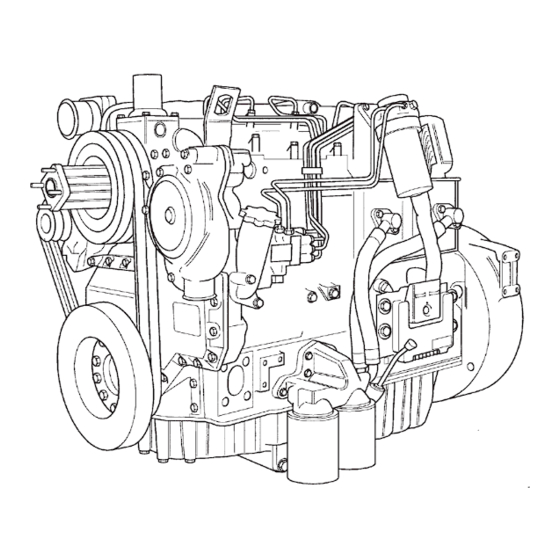
1100 Series model VK General information Introduction This Workshop Manual has been written to provide assistance in the service and overhaul of the Perkins 1100 Series six cylinder, (model VK) engines. For overhaul procedures the assumption is made that the engine is removed from the application. - Page 15 1100 Series model VK Engine views (side mounted turbo) R1310 R1311 Workshop Manual, TPD 1476E, Issue 1...
- Page 16 1100 Series model VK Engine views (top mounted turbo) R1312/1 R1313 Workshop Manual, TPD 1476E, Issue 1...
-
Page 17: Engine Identification
1100 Series model VK Engine identification The Perkins 1100 Series engines have been designed for agricultural, industrial and construction applications. Model VK are all turbocharged engines. The correct identification of the engine is by the full engine number. The engine number is stamped on a label which is fastened to the left side (A2) of the cylinder block. An... - Page 18 1100 Series model VK Safety precautions These safety precautions are important. You must refer also to the local regulations in the country of use. Some items only refer to specific applications. l Only use these engines in the type of application for which they have been designed. l Do not change the specification of the engine.
- Page 19 1100 Series model VK l Do not clean an engine while it runs. If cold cleaning fluids are applied to a hot engine, certain components on the engine may be damaged. l Fit only genuine Perkins parts, failure to do so may damage the engine and effect the warranty. l To prevent damage to the ECM.
- Page 20 1100 Series model VK Engine lift equipment The maximum weight of the engine without coolant, lubricant or a gearbox fitted will vary for different applications. It is recommended that lift equipment with a minimum capacity of 600 kg (1320 lbs) is used. Before the engine is lifted: l Always use lift equipment of the approved type and of the correct capacity to lift the engine.
-
Page 21: Viton Seals
1100 Series model VK Viton seals Some seals used in engines, and in components fitted to engines, are made of Viton. Viton is used by many manufacturers and is a safe material under normal conditions of operation. If Viton is burned, a product of this burnt material is an acid which is extremely dangerous. Never allow this burnt material to come into contact with the skin or with the eyes. - Page 22 1100 Series model VK POWERPART recommended consumable products Perkins have made available the products recommended below in order to assist in the correct operation, service and maintenance of your engine and your machine. The instructions for the use of each product are given on the outside of each container.
- Page 23 1100 Series model VK POWERPART Silicone adhesive An RTV silicone adhesive for application where low pressure tests occur before the adhesive sets. Used for sealing flange where oil resistance is needed and movement of the joint occurs. Part number 21826038. POWERPART Silicone RTV sealing and jointing compound Silicone rubber sealant that prevents leakage through gaps.
- Page 24 1100 Series model VK Abbreviations The abbreviations used in this manual are as follows: CCB ..................Closed Circuit Breather System ECM.
- Page 25 This page is intentionally blank...
-
Page 26: Specifications
1100 Series model VK Specifications Basic engine data Number of cylinders....................... 6 Cylinder arrangement .. -
Page 27: Data And Dimensions
1100 Series model VK Data and dimensions Note: This information is given as a guide for personnel engaged on engine overhauls. The dimensions which are shown are those which are mainly used in the factory. The information applies to all engines. Cylinder head Angle of valve seat: - Intake ... - Page 28 1100 Series model VK Intake and exhaust valves Intake valves Diameter of valve stem ............8,953/8,975 mm (0.3525/0.3533 in) Clearance in valve guide ............0,025/0,069 mm (0.0010/0.0027 in) Maximum permissible clearance in valve guide: - Production limit..
- Page 29 1100 Series model VK Dimensions of recesses for valve seat inserts Intake A1................. 10,585/10,715 mm (0.4167/0.4219 in) A2...
- Page 30 1100 Series model VK Valve guides and valve springs Valve guides Inside diameter of partially finished guide ........8,600/8,700 mm (0.3386/0.3425 in) Inside diameter of finished guide..........9,000/9,022 mm (0.3543/0.3552 in) Outside diameter: - Intake.
- Page 31 This as a preview PDF file from best-manuals.com Download full PDF manual at best-manuals.com...
Need help?
Do you have a question about the Perkins 1100 Series and is the answer not in the manual?
Questions and answers