
Related Manuals for Mastip CTI Series


Summary of Contents for Mastip CTI Series
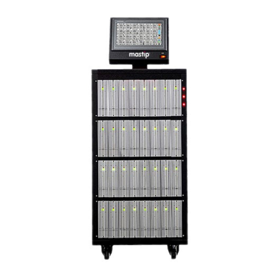
- Page 1 Temperature controller CTI Series CTI Series Temperature & Sequential Valve Gate Controller User Guide Copyright Mastip Technology Limited. Information Subject to Alteration V4.3 www.mastip.com...
-
Page 2: Table Of Contents
SAFETY ................................- 4 - CAUTIONS ................................- 5 - Chapter 1 Introduction ............................- 5 - 1.1 CTI Series Mainframe Configurations ....................- 5 - 1.2 Control Modules ............................ - 6 - 1.3 Specifications ............................. - 6 - 1.4 Features ............................. - 7 - 1.5 Typical Thermocouple &... - Page 3 7.7 Preview the Setting ..........................- 61 - Chapter 8 Run/Stop System ..........................- 62 - 8.1 Run System ............................- 62 - 8.2 Stop System ............................- 62 - Copyright Mastip Technology Limited. Information Subject to Alteration V4.3 www.mastip.com...
-
Page 4: Warranty
Temperature controller CTI Series WARRANTY We warrant that this product will be free from defects in materials and workmanship for a period of two (2) years from the date of shipment. If any such product proves defective during this warranty period, we, at our option, either will repair the defective product without charge for parts and labor, or will provide a replacement in exchange for the defective product. -
Page 5: Cautions
30 seconds. Chapter 1 Introduction 1.1 CTI Series Mainframe Configurations The CTI controller is made up of 3 different models of mainframes depending on the number of zones required. These are referred to as CTI-100, CTI-200, CTI-300. -
Page 6: Control Modules
Temperature controller CTI Series 1.2 Control Modules The main frames are available with 2 styles of control modules depending on the requirements. The modules are fully interchangeable across all mainframe designs. The externally mounted heat sink and integrated design reduce maintenance cost and downtime. -
Page 7: Features
Temperature controller CTI Series Temperature Control Control Mode Auto-PID / Manual Measurement Range 0~500℃(32~932℉) Output Control Zero Cross / Phase Angle Setting Range 0~450℃(32~842℉) ℉ or ℃, J or K-Type, Thermocouple Temperature Unit software selectable software selectable Calibration Accuracy ±0.25% FS Control Stability ±1digit-under steady state... -
Page 8: Typical Thermocouple & Mold Power Output Connector Wiring
Temperature controller CTI Series 1.5 Typical Thermocouple & Mold Power Output Connector Wiring The system can be supplied with either European style or US style power and Thermocouple mold connectors, typically wired as follows (Custom wiring available) Thermocouple & Mold Power Combination Wiring... - Page 9 Temperature controller CTI Series Valve Gate Output Wiring (European style 24 pin series “A “) Signal Pins Description Type Sees a closed condition or DC24V as a signal to start the Normally Open Dry Contact Trigger Input 1 & 2...
-
Page 10: Remote Input & Alarm Output Connectors Wiring
Temperature controller CTI Series 3-Ph+E (4 wire) 200-240Vac 1.7 Remote Input & Alarm Output Connectors Wiring (Where specified) Remote Input Wiring Alarm & Normal Output Wiring Signal Pins Description Type After a delay time (adjustable) since the contact is closed,... -
Page 11: Chapter 2 Inspection & Installation
Chapter 2 Inspection & Installation 2.1 Unpacking and Inspection 1. After unpacking, inspect the mainframe and check for any damage that may have occurred during shipment. 2. Check the circuit breaker disconnect and neon phase voltage indicators for damage. 3. Check for proper operation of circuit breaker by flipping breaker on and off with no voltage applied. -
Page 12: Connecting The Power Cable (Cti-200/Cti-300)
Temperature controller CTI Series 2.4 Connecting the Power Cable (CTI-200/CTI-300) 1. Select the power input wire size according to the load power, and the national and local electrical codes. (if required) 2. Remove the metal cover of the power input terminal block by removing screws around its perimeter. -
Page 13: Chapter 3 Connecting The System To The Mold
Temperature controller CTI Series Chapter 3 Connecting the System to the Mold 3.1 Prior to Start Up ● Check that the system is completely disconnected from the power source. ● Clean up any water, oil, dirt, cleaning fluids etc. that may have spilled during a mold change or since the last production run. - Page 14 Temperature controller CTI Series 6. Load a mold setup (if required). 7. Checking the mold setup zone by zone on HMI. 8. Correct any faults found during diagnostics. 9. Touch “Run” to start the system. 10. Check that the controller is functioning correctly.
-
Page 15: Chapter 4 Operator Interface
Temperature controller CTI Series Chapter 4 Operator Interface 4.1 Main Interface The main interface is used to monitor, log in the system and general operations. 4.1.1 Temperature Control Icon Button Mode, 24 zone per page Resolution 0.1 is not checked Icon Button Mode, 42 zone per page Resolution 0.1 is checked... -
Page 16: Temperature Zone Introduction
Temperature controller CTI Series ● Function Button: Icon mode is the default setting. Text mode can be selected on system setting page. ● 24 or 42 zones per page: 24-zone is the default setting, can be alternated on system setting page ●... -
Page 17: Multiple Temperature Zone Selection
Temperature controller CTI Series ● displayed in color in stop state ● if thermocouple is open, 999 will be displayed ● if zone is turned off, is displayed in red color ● blinking when communication fails ● Touch it to set zone’s parameters and operate it. -
Page 18: Sequence Valve Gate Control
Temperature controller CTI Series 4.1.4 Sequence Valve Gate Control [Stop]: (red) Stop valve gate control of all zones. [Run]: (green) Run valve gate control of all zones. [Auto] / [Manual]: Place the valve gate control of all zones in Auto / Manual mode. -
Page 19: Usb Port
4.2 USB Port The USB port on the CTI series is intended to be used to copy mold setup files to and from the system. The screen for importing or exporting mold setups is displayed in the Group Setup Screen. -
Page 20: Chapter 5 User Authority & System Setting
Temperature controller CTI Series Chapter 5 User Authority & System Setting 5.1 Login / Logout the System & User Authority To avoid accidental changes and protect the system data, the controller is set up with different operator levels which have different security authorities. - Page 21 Temperature controller CTI Series ● Set ‘timeout logout’ automatically. After inputting password, you can choose Logout type, “Online timeout” and “Idle timeout”. You can set the time, for example, 10 minutes. If no operation after 10 minutes, the system will turn to be non-login status.
- Page 22 Temperature controller CTI Series ● Set data storage interval time ● Relieve alarm buzzer ● View history curve, export data ● View system log, operation records ● All authorities of Engineers. ● Manage operator and engineer users ● Modify zone id, set zone color ●...
-
Page 23: System Setting
Temperature controller CTI Series 5.2 System Setting Touch icon [System] on the main interface of temperature control, then enter the System Setting Screen. 5.2.1 Security ● Authorization: You can manage users, include add, copy and delete users. You can also check the user’s properties. - Page 24 Temperature controller CTI Series ● Change Password: You can change the password for the current user by “Edit user”. ● Authorized to Change Setpoint/ Everyone Can Change Setpoint: Touch it to change the authority setting for operators’ login. - 24 -...
- Page 25 Temperature controller CTI Series Display Authorized to Change Setpoint Current setting is everyone can change Setpoint. Operators not logged in the system can run/stop the system and change the setpoint Display Everyone Can Change Setpoint: Current setting is authorized to Change the setpoint.
-
Page 26: Time
Temperature controller CTI Series 5.2.2 Time For the system time initialization, the setting method is: 1) Touch the parameters required to set, then input the value on the screen keyboard. 2) Touch the [OK] to finish the modification. NOTE: If no response after you Touchs the parameter values, it indicates that this parameter cannot be modified. -
Page 27: Control Modules
Temperature controller CTI Series 5.2.6 Control Modules Display the communication status of each module and its type. ● Software version: View current system software version. 5.2.7 Auxiliary Functions Touch , to enter Auxiliary function configuration page. Remark: ( red = unchecked,... - Page 28 Temperature controller CTI Series ● Alarm Output Setting For 15 common faults (T/C Broken, Load Shorted, Over Temp, over voltage, etc.), customers can choose to connect some or all of the faults to an external alarm output device. When the selected fault occurs, the system will give a relay output signal to drive the external devices work.
-
Page 29: 42-Zone / 24-Zone Display Shifting
Temperature controller CTI Series Mold Self-inspection You can do self-inspection on multiple heating zones of the mold one by one before working. Set the start ID and end ID (maximum 100) to determine the scope of the test. Set the maximum working temperature to limit the temperature rise and prevent accidents. -
Page 30: Speed Related Setting
Temperature controller CTI Series This function can be enabled or disabled according to requirements. 1) Touch the [Sensor Fault Solution] to enter to setting interface. 2) Set Fault ID and Related ID. You can set 12 groups at most. 3) Touch the [Enable] or [Disable] to open or stop this function. - Page 31 Temperature controller CTI Series When the system starts, the first group will work. When each zone’s temperature arrives at the target value (the tolerance can be set), the second group will work. Then the third and the fourth group in turn.
-
Page 32: Help
Temperature controller CTI Series 5.2.12 Help Touch [Help],to get the helps on the operation. 5.2.13 Back Touch [Exit], to go back to the main interface. - 32 -... -
Page 33: Chapter 6 Temperature Control Operations
Temperature controller CTI Series Chapter 6 Temperature Control Operations 6.1 Control Modes [Auto] This type of control is a “closed loop” system and requires a thermocouple feedback signal. The controller uses a PID algorithm to determine the required output power to hold the actual temperature value equal to the set value. -
Page 34: Detail Parameters For Each Zone
Temperature controller CTI Series During soft start, the output power step up from 0% until the temperature rises to 100°C (212°F) and holds it. When soft start time is over, the controller will return to normal work mode. Soft start condition: a) The soft start function is on (parameter Soft Start =1~10). - Page 35 Temperature controller CTI Series Misconnection of heater & sensor diagnostic function. T/C Error 0 – Off. Detection 1 – Checking the heater after power on, if it’s judged as sensor, controller will alarm and cut off output to protect it..
-
Page 36: Zone Setting
Temperature controller CTI Series Heater Life _____W (the remaining life of the heater) System calculates automatically, cannot be set by manual Setpoint Min The target temperature value cannot be less than the lower limit Setpoint Max The target temperature value cannot exceed the upper limit value 6.4 Zone Setting... -
Page 37: Director / Administrator Login Status
Temperature controller CTI Series 6.4.3 Director / Administrator Login Status - 37 -... - Page 38 Temperature controller CTI Series ● Change ID Name:Touch it to call up small keyboard and rename the zone you want. ● Set output power percent in Manual mode: Touch Manual to call up small keyboard. ● Change General parameters: Touch Setpoint to call up small keyboard.
-
Page 39: Group Config & Tools
Temperature controller CTI Series 6.5 Group Config & Tools Touch [Group] on the main interface, enter to the Group Configuration & Tools Management. [Graph]: Check Present Curve and History Curve. (see Chapter 6.6) 6.5.1 Group Setting Parameters for zones with the same background color can be set all together. -
Page 40: Tools Management
Temperature controller CTI Series 3) Touch [Setpoint] or [Alarm High] or [Alarm Low] to call up small keyboard. 4) Input the required value. 5) Touch [OK] to complete the setting. f there is no response when you touch the parameter’s value, it means the parameter cannot NOTE: I be changed or the authority is not enough. - Page 41 Temperature controller CTI Series 1. Input a new pattern name in the box. 2. Touch the [Save] to save the name of the new pattern name. Zones’ On/Off state, auto/manual control mode, and the background color will be also saved in the pattern file.
- Page 42 Temperature controller CTI Series You can browse the tool files in USB disk or locally, and manage these files. ● Files location selected: [Local File] or [USB File]. ● [Delete]: used to delete the selected file. [Import]: used to import the files selected from the USB disk to the local.
-
Page 43: Back
Temperature controller CTI Series 6.5.3 Back Touch [Exit], back to the main interface. 6.6 Graph Touch [Graph] on the main interface of [Group], then you can enter to the Real Time Display Screen. - 43 -... -
Page 44: Real-Time Curve
Temperature controller CTI Series You can select 6 zones max. to view the real-time curve. Touch [History] on this screen to enter to the History Curve Display. Touch [Exit] back to the main interface. 6.6.1 Real-time Curve 6.6.1.1 Select Zone ID to View On Present Curve Screen, you can view max. - Page 45 Temperature controller CTI Series 6.6.2.1 Select Zone ID to View We you Touch [History] on present curve screen, History Curve ID selection interface will be displayed. Each History Curve ID group can display 10 zones. Select the ID group to view, or back to real time curve by [Quit].
- Page 46 Temperature controller CTI Series 6.6.2.3 Select the Curve Start Time When you enter History Curve interface, the curve start time is 2 hours ago. And display time length of the abscissa (X axis) is 2 hours. You can Touch on...
- Page 47 Temperature controller CTI Series 6.6.2.4 Zoom In &Zoom out the Curve. You can adjust the scale of X/Y axis with the sliding bar, to zoom in or zoom out the curve. 6.6.2.5 View Other Zones You can view the history curve of other zones by Touching [PgDn] or [PgUp].
-
Page 48: Alarms
Temperature controller CTI Series 6.7 Alarms Touch [Alarm] on the main interface, enter to the Alarm History interface. 6.7.1 Alarm Record 6.7.1.1 Select the Record Period You can touch the Start Time window to input a new one (the date format should be same as the original one). -
Page 49: Alarm Status
Temperature controller CTI Series 6.7.3 Alarm Status Alarm Code Description Solution Thermocouple is broken. Check the sensor or switch to manual T/C Broken Controller will shut off the output. mode Thermocouple is reversed. Check the sensor or switch to manual T/C Reversed Controller will shut off the output. -
Page 50: Simple Working Mode
Temperature controller CTI Series Temperature of control cards in the Check the modules and the fans in the CC Over Temp mainframe is over high alarm value mainframe. Output percent exceeds (Normal Power + Leakage Leakage detection) %, the controller will Check the mold, clean the leakage. -
Page 51: Working Mode Selection
Temperature controller CTI Series 6.8.1 Working mode selection. ● Touch [Working mode] to enter to working mode selection interface. ● This interface shows the ID of temperature zone/current working mode/setpoint value. ● Touch [PG+]/[PG-] on the right side to view more temperature zones. - Page 52 Temperature controller CTI Series ● After running the zones, Touch [Working mode] below and in pop-up window you can choose [Stop/Auto/Manual/Standby] to switch the working mode. ● Touch [Setpoint] to modify temperature value in pop-up window. - 52 -...
-
Page 53: Soft Start Setting
Temperature controller CTI Series 6.8.2 Soft Start Setting ● Touch [Soft Start] to enter to soft start setting interface. ● Touch [Select All] to select all zones or select some zones. ● Touch [Soft-start Setting] below and set duration of soft start in pop-up window. - Page 54 Temperature controller CTI Series [J/K]: Touch to switch the thermocouple type. [T/C Error Detection]: Touch to select the sensor fault detection level. ● OFF: (Sensor no detection): Turn off the detection function. ● Lever 1: (Sensor primary detection): Detect the load impedance; when an abnormality is found, it is judged as a wrong connection and an alarm is triggered.
-
Page 55: Chapter 7 Sequential Valve Gate Control Operations
Temperature controller CTI Series Chapter 7 Sequential Valve Gate Control Operations Touch [SVG] on Temperature Control main interface, then you can enter to Sequence Valve Gate Control main interface. Note: page down to the last page of temperature zones. And Touch [Temp] on Sequence Valve Gate Control main interface, then you can enter Temperature Control main interface. -
Page 56: Start Trigger Modes
Temperature controller CTI Series 7.2 Start Trigger Modes This Sequential Valve Gate controller supports gates open/close 1~2 times in a complete cycle. If the start trigger duration time is longer than a complete cycle of gate open/close, then the control... - Page 57 Temperature controller CTI Series position. 2) Gates open after T1 time (or screw position is T1) from the controller receives start trigger; 3) Gates close after T2 time (or screw position is T2) from the gates open; 4) Gates open again after T3 time (or screw position is T3) from the gates close.
- Page 58 Temperature controller CTI Series 1) When the controller receives the start trigger, it initiates the run timer from the zero-time position. 2) Gates open after T1 time (or screw position is T1) from the controller receives start trigger; 3) Gates close after T2 time (or screw position is T2) from the gates open;...
-
Page 59: Gate Open/Close Trigger Modes
Temperature controller CTI Series 7.3 Gate Open/Close Trigger Modes You have two main options that you can use to set up gate opening and gate closing times. 1) Time value only– if you have no ancillary sensors then your only choice for gate opening and closing is an internal timer. -
Page 60: Engineer / Director / Administrator Login Status
Temperature controller CTI Series 7.5.2 Engineer / Director / Administrator Login Status ● ID name: Touch it to call up small keyboard and rename the zone you want. ● Select gate open/close trigger modes: Touch the indicator of Time control or Screw control to select modes for T1~T4. -
Page 61: Test
Temperature controller CTI Series Select a color you want to use as background of this gate, and then Touch [YES] to set the figures and exit the interface. ● Screw Position Setup: Touch to call up screw position setup window. -
Page 62: Chapter 8 Run/Stop System
Temperature controller CTI Series Chapter 8 Run/Stop System 8.1 Run System Touch [Run] on the main interface to run the temperature control or SVG control system. Temperature Control All zones start to work in Auto mode (disable keep the data in system setting) or the mode before All temperature zones work in auto control mode when started, except for those turned off in temperature zone Settings.
Need help?
Do you have a question about the CTI Series and is the answer not in the manual?
Questions and answers