Table of Contents
Advertisement
Quick Links
Advertisement
Table of Contents

Subscribe to Our Youtube Channel
Related Manuals for Mastip METICOM CTI Series


Summary of Contents for Mastip METICOM CTI Series
- Page 1 METICOM CTI Series Temperature & Sequential Valve Gate Controller User Guide...
-
Page 2: Warranty
Do not operate this product when wet. Do not operate this product in an explosive atmosphere. Page | - 1 - © Copyright Mastip Technology Limited. Information subject to alteration. V1.01 www.mastip.com... -
Page 3: Chapter 1 Introduction
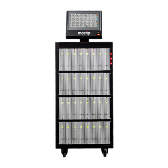
The mainframes are available with 2 styles of control modules depending on requirements. The modules are fully interchangeable across all mainframe designs. The externally mounted heat sink and integrated design reduce maintenance cost and downtime. Page | - 2 - © Copyright Mastip Technology Limited. Information subject to alteration. V1.01 www.mastip.com... -
Page 4: Specifications
3-Ph+E (4 wire) 200-240Vac Power Supply 3-Ph+N+E (5 wire) 380-415Vac Working Conditions 0~55℃ (32~131℉), 10~80%RH (No condensing) Storage Conditions -20~70℃ (-4~158℉), 10~80%RH (No condensing) Temperature Control Page | - 3 - © Copyright Mastip Technology Limited. Information subject to alteration. V1.01 www.mastip.com... - Page 5 Triac breakdown All zones’ temperature in tolerance output (optional) Power supply over-voltage Start sequence in group Cabinet temperature over-setting Sensor fault solution Alarm output (optional) Page | - 4 - © Copyright Mastip Technology Limited. Information subject to alteration. V1.01 www.mastip.com...
- Page 6 (custom wiring available) Separate Power & Thermocouple Connectors (European style 24 pin series “E”) Separate Power & Thermocouple Connectors (US style 25 pin series ”A”) Page | - 5 - © Copyright Mastip Technology Limited. Information subject to alteration. V1.01 www.mastip.com...
- Page 7 Position A calibration routine within the controller adjusts actual input to actual screw position. Valve Gate Output Wiring (European style 24 pin series “A”) Page | - 6 - © Copyright Mastip Technology Limited. Information subject to alteration. V1.01 www.mastip.com...
-
Page 8: Power Input Wiring
The CTI temperature controllers can be connected to either 3-phase 4-wire Y / Δ type (200-240Vac) or 3-phase 5-wire Y type (380-415Vac) mains power supplies. 3-Ph+N+E (5 wire) 380-415Vac 3-Ph+E (4 wire) 200-240Vac Page | - 7 - © Copyright Mastip Technology Limited. Information subject to alteration. V1.01 www.mastip.com... -
Page 9: Chapter 2 Inspection & Installation
The label indicates the input voltage configuration that was prewired at the factory. Page | - 8 - © Copyright Mastip Technology Limited. Information subject to alteration. V1.01 www.mastip.com... - Page 10 2.3 Connecting the HMI (Standalone HMI only) 1. Place or mount the HMI on the position required. 2. Connect the HMI and the mainframe with communication cable. Page | - 9 - © Copyright Mastip Technology Limited. Information subject to alteration. V1.01 www.mastip.com...
- Page 11 Do not connect the power input cord to your power distribution system until the back terminal block cover is securely in place. Ensure the chassis has been earth grounded before applying power. Page | - 10 - © Copyright Mastip Technology Limited. Information subject to alteration. V1.01 www.mastip.com...
-
Page 12: Chapter 3 Connecting The System To The Mold
(if required). 2. Connect the controller to the power source. 3. Switch the circuit breakers ON. 4. Turn on the HMI, then select the language. Page | - 11 - © Copyright Mastip Technology Limited. Information subject to alteration. V1.01 www.mastip.com... -
Page 13: Chapter 4 Operator Interface
The main interface is used to monitor, log in the system and general operations. 4.1.1 Temperature Control Icon Button Mode, 24-zone per page, Resolution 0.1 is not checked per page, Resolution 0.1 is checked Page | - 12 - © Copyright Mastip Technology Limited. Information subject to alteration. V1.01 www.mastip.com... - Page 14 ● output percent setting will be displayed in manual mode, e.g. No.1 zone. ● click setting value, output percent and load current can be alternated to show in 42-zone page. Page | - 13 - © Copyright Mastip Technology Limited. Information subject to alteration. V1.01 www.mastip.com...
- Page 15 [Group]: Enter the group/global setting, pattern/mold files management, and language selected. [System]: Enter the system setting. [Login]/[Logout]: Log in/out of the system to achieve the different security authority. 4.1.2 Sequential Valve Gate Control Page | - 14 - © Copyright Mastip Technology Limited. Information subject to alteration. V1.01 www.mastip.com...
- Page 16 The USB port is also be used to export the historical data record (in csv format) from the system. The screen for exporting data record is displayed in the History Data Curve Screen. Page | - 15 - © Copyright Mastip Technology Limited. Information subject to alteration. V1.01 www.mastip.com...
- Page 17 Only supports USB disks that use a File Allocation Table (FAT or FAT32) format. Only supports USB versions 2.0 and 1.1. Use an empty USB disk or one that contain as few files as possible. Page | - 16 - © Copyright Mastip Technology Limited. Information subject to alteration. V1.01 www.mastip.com...
-
Page 18: Chapter 5 Security & System Setting
“Operator”. Check the system log. Clear all data records. Select display resolution, button mode, etc. Set temperature setpoint or unit globally. Page | - 17 - © Copyright Mastip Technology Limited. Information subject to alteration. V1.01 www.mastip.com... -
Page 19: System Setting
Auxiliary functions setting. 5.2 System Setting Touch [System] on the main interface of temperature control, then enter the System Setting Screen. Page | - 18 - © Copyright Mastip Technology Limited. Information subject to alteration. V1.01 www.mastip.com... - Page 20 For the system time initialization, the setting method is: 1) Click the parameter you wish to set, then input the value on the screen keyboard. Page | - 19 - © Copyright Mastip Technology Limited. Information subject to alteration. V1.01 www.mastip.com...
- Page 21 ● Keep the data: Zones’ work state (Auto or Manual, and power output % in manual mode) will be the same as previous when the system re-started. Page | - 20 - © Copyright Mastip Technology Limited. Information subject to alteration. V1.01 www.mastip.com...
-
Page 22: Auxiliary Functions
When the sensor of the zone (Major ID) fails the controller will use the temperature of the other zone (Related ID) to simulate the failed one. This function can be enabled or disabled according to requirements. Page | - 21 - © Copyright Mastip Technology Limited. Information subject to alteration. V1.01 www.mastip.com... - Page 23 This function can be enabled or disabled according to requirements. 1) Click the [Speed Related Setting] to enter its setting interface. Page | - 22 - © Copyright Mastip Technology Limited. Information subject to alteration. V1.01 www.mastip.com...
- Page 24 5.2.12 Help Touch [Help] to get help on the operation. 5.2.13 Back Touch [Exit] to go back to the main interface. Page | - 23 - © Copyright Mastip Technology Limited. Information subject to alteration. V1.01 www.mastip.com...
-
Page 25: Chapter 6 Temperature Control Operations
This function only can be selected by zone setting. Note To start PID auto-tuning function, present temperature value should be lower than set point. : Page | - 24 - © Copyright Mastip Technology Limited. Information subject to alteration. V1.01 www.mastip.com... - Page 26 Sensor correction is made by adding it to measured value. Cold-junction Ambient temperature high alarm value, unit is same as parameter C/F Temp setting. High-alarm 0 – Off. Page | - 25 - © Copyright Mastip Technology Limited. Information subject to alteration. V1.01 www.mastip.com...
- Page 27 When the power supply voltage is over about (setting×4.5+210)V, the Over-Voltage controller will alarm and cut off output. Recommended setting is VoL=13 (over-voltage is about 270Vac). Page | - 26 - © Copyright Mastip Technology Limited. Information subject to alteration. V1.01 www.mastip.com...
-
Page 28: Group Setting
1) Click [Group Config], the background color window will appear. 2) Select the background color of zones you want to set parameters, the setting page will appear. Page | - 27 - © Copyright Mastip Technology Limited. Information subject to alteration. V1.01 www.mastip.com... - Page 29 : The mold pattern file is a database file containing the control parameters of each zone. NOTE 6.4.2.1 New Pattern’s Config Export 1. Enter a new Pattern Name in the box. Page | - 28 - © Copyright Mastip Technology Limited. Information subject to alteration. V1.01 www.mastip.com...
- Page 30 Click the [Pattern Files Management] to enter the management screen. You can browse the pattern files stored in a USB disk or in the local storage and manage these files. Page | - 29 - © Copyright Mastip Technology Limited. Information subject to alteration. V1.01 www.mastip.com...
- Page 31 You can change language by touch the related language button. : You need to re-start HMI after changing the language, or some functions maybe abnormal. NOTE Page | - 30 - © Copyright Mastip Technology Limited. Information subject to alteration. V1.01 www.mastip.com...
-
Page 32: Zone Setting
[Auto] or [Manual], and then confirm it. ● Set power output percent in Manual mode: click it to call up small keyboard. ● Back to main interface: touch [Quit]. Page | - 31 - © Copyright Mastip Technology Limited. Information subject to alteration. V1.01 www.mastip.com... -
Page 33: Graph Display
You can select 6 zones to view the real-time curve. And you can touch [History] on this screen to enter the History Curve Display. Page | - 32 - © Copyright Mastip Technology Limited. Information subject to alteration. V1.01 www.mastip.com... - Page 34 1) Click the ID number to enter curve’s ID selection mode. 2) Input the ID number which you want to view the curve, and then click [YES] to confirm. Page | - 33 - © Copyright Mastip Technology Limited. Information subject to alteration. V1.01 www.mastip.com...
- Page 35 The system can save the temperature data in the latest 15~30 days. 6.6.2.1 Select Zone ID to View When you touch [History] on present curve screen, History Curve ID Selection interface will be displayed. Page | - 34 - © Copyright Mastip Technology Limited. Information subject to alteration. V1.01 www.mastip.com...
- Page 36 The box before the ID number is used to select the curve display. Blue – unchecked, green – checked You can click it. The curve’s color is same as the color of ID number. Page | - 35 - © Copyright Mastip Technology Limited. Information subject to alteration. V1.01 www.mastip.com...
- Page 37 Do not remove the USB disk from the system during the writing operation. 6.6.2.7 Back to Present Curve Touch the [Quit] to go back to the present curve screen. Page | - 36 - © Copyright Mastip Technology Limited. Information subject to alteration. V1.01 www.mastip.com...
-
Page 38: Alarm Record
When the zones alarm is cleared, the mute function of this zone is reset. When an alarm has been muted, new alerts for the same zone will trigger the alarm again. Page | - 37 - © Copyright Mastip Technology Limited. Information subject to alteration. V1.01 www.mastip.com... -
Page 39: Alarm Status
Load current is too high. Check the heater and the Rated current setting. Check the heater and replace the fuse. Fuse blown Fuse is blown. Page | - 38 - © Copyright Mastip Technology Limited. Information subject to alteration. V1.01 www.mastip.com... - Page 40 Check the power supply. Related to parameter “Cold-junction Temp Cold-junction Temperature is over High-alarm”. Over Temp alarm setting. Check the module and the fans of mainframe. Page | - 39 - © Copyright Mastip Technology Limited. Information subject to alteration. V1.01 www.mastip.com...
-
Page 41: Chapter 7 Sequential Valve Gate Control Operations
From this point gates open and close according to the time or position settings that you have configured. [Manual] This type of control requires no start trigger signal. Each gate can be opened or closed by touching [MANUAL]. Page | - 40 - © Copyright Mastip Technology Limited. Information subject to alteration. V1.01 www.mastip.com... - Page 42 Mode 0: Once the gate open/close cycle starts, it will ignore the new start trigger until the cycle ends. The control process is similar to the start trigger time of duration is longer than a complete cycle of gate open/close. Page | - 41 - © Copyright Mastip Technology Limited. Information subject to alteration. V1.01 www.mastip.com...
- Page 43 4) Gates open again after T3 time (or screw position is T3) from the gates close; 5) Gates close after T4 time (or screw position is T4) from the gates open; Page | - 42 - © Copyright Mastip Technology Limited. Information subject to alteration. V1.01 www.mastip.com...
- Page 44 Mode 3: The gate open/close cycle will be terminated and gate close when the new start trigger comes. The controller initializes the run timer when it receives the next new start trigger. Page | - 43 - © Copyright Mastip Technology Limited. Information subject to alteration. V1.01 www.mastip.com...
- Page 45 Gate open delay time (or screw position) from the controller receives start trigger. Gate open duration time (or screw position for gate closing). Gate open again delay time (or screw position) from it close. Page | - 44 - © Copyright Mastip Technology Limited. Information subject to alteration. V1.01 www.mastip.com...
-
Page 46: Gate Setup
● Back to main interface: touch [Quit]. 7.5.2 Engineers or Administrators Login Status ● Screw Position Setup: touch to call up screw position setup screen. Page | - 45 - © Copyright Mastip Technology Limited. Information subject to alteration. V1.01 www.mastip.com... - Page 47 When you are satisfied that all is good, touch [Quit] to set the figures and leave the screen. ● Select background color of this gate: touch [Color] to call up background color setting. Page | - 46 - © Copyright Mastip Technology Limited. Information subject to alteration. V1.01 www.mastip.com...
-
Page 48: Chapter 8 Run/Stop System
(enable keep the data in system setting) except the module is turned off by zone setting. ● You can touch [Standby]on the main interface to make all zones wok in Standby mode. Page | - 47 - © Copyright Mastip Technology Limited. Information subject to alteration. V1.01 www.mastip.com... - Page 49 ● You can Stop a specified zone by Zone Setting. ● You can Stop a group of zones with the same background color by Global Config. Page | - 48 - © Copyright Mastip Technology Limited. Information subject to alteration. V1.01 www.mastip.com...
Need help?
Do you have a question about the METICOM CTI Series and is the answer not in the manual?
Questions and answers