Table of Contents
Advertisement
Quick Links
Advertisement
Table of Contents

Related Manuals for Mastip METICOM TM10


Summary of Contents for Mastip METICOM TM10
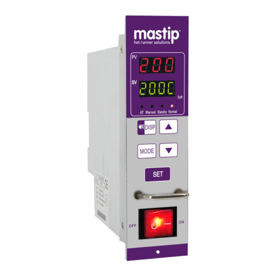
- Page 1 Hot-Runner Temperature Controller with METICOM TM10 module User Guide Ver. 1.01...
-
Page 2: Warranty
Never allow the fan outlets on the unit become blocked, this is where the system's cooling airflow exits. If this area of the mainframe becomes cluttered and insufficient airflow or the system maybe damaged. Page | - 2 - © Copyright Mastip Technology Limited. Information subject to alteration. V3.51a www.mastip.com... -
Page 3: General Description
WARNING: Before applying power, make sure all international and local electrical codes have been followed and all safety precautions are taken. IMPORTANT: For mold wiring and heater connection information, refer to mold connector wiring diagram. Page | - 3 - © Copyright Mastip Technology Limited. Information subject to alteration. V3.51a www.mastip.com... -
Page 4: Back Panel Wiring
Temperature Controller METICOM TM10 Module 4. BACK PANEL WIRING Page | - 4 - © Copyright Mastip Technology Limited. Information subject to alteration. V3.51a www.mastip.com... -
Page 5: Typical System Wiring Diagram
Temperature Controller METICOM TM10 Module 5. TYPICAL SYSTEM WIRING DIAGRAM Page | - 5 - © Copyright Mastip Technology Limited. Information subject to alteration. V3.51a www.mastip.com... - Page 6 Combination Power & Thermocouple Connector (16 or 24 Pin) Separate Power & Thermocouple Connector (16 or 24 Pin) Separate Power & Thermocouple Connector (25 Pin) Page | - 6 - © Copyright Mastip Technology Limited. Information subject to alteration. V3.51a www.mastip.com...
-
Page 7: Module Operation
◆ Control output device: Triac ◆ Load capability: 15A, 50W~1650W(110V), 100W~3600W(240V) ◆ Operating temperature: 0℃~55℃ (32℉~131℉) ◆ Operating humidity: 10~80%, non-condensing ◆ Storage temperature: -20℃~70℃ (-4℉~158℉) Page | - 7 - © Copyright Mastip Technology Limited. Information subject to alteration. V3.51a www.mastip.com... - Page 8 1) Change the parameter value: Press ∧、∨to modify the value, and press SETto save it, then the next parameter and its PV displays parameter name and SV displays the parameter’s value. In this mode, you can Page | - 8 - © Copyright Mastip Technology Limited. Information subject to alteration. V3.51a www.mastip.com...
- Page 9 The process temperature is less than 100°C (212°F). Terminate soft start process: The soft start process can be terminated by pressing MODE key (when boS=1). Page | - 9 - © Copyright Mastip Technology Limited. Information subject to alteration. V3.51a www.mastip.com...
- Page 10 SuP> 900, the controller executes auto-tune function by making setting value as target. SuP = 453 or SuP = 845, PID self-adjusting function is on. 8) nSL: Manual/Auto control mode. Page | - 10 - © Copyright Mastip Technology Limited. Information subject to alteration. V3.51a www.mastip.com...
- Page 11 0: Off. 1~10: Checking the load current when output is HEA×10%, if the controller judge the heater fault, it will alarm. Recommended setting is HEA=3~5. Page | - 11 - © Copyright Mastip Technology Limited. Information subject to alteration. V3.51a www.mastip.com...
- Page 12 12) SoL: state of soft-start indicator. 0: Blink; 1:Always-on. 1: Change rapidly by ∧and∨ keys. 13) SVP: Target temperature setting mode. 0: By parameter “SV”; Page | - 12 - © Copyright Mastip Technology Limited. Information subject to alteration. V3.51a www.mastip.com...
-
Page 13: Alarm Messages
H o t high Over voltage Check the power supply. H HH F u S —— Fuse Blowout Check the load and replace the fuse. Page | - 13 - © Copyright Mastip Technology Limited. Information subject to alteration. V3.51a www.mastip.com...
Need help?
Do you have a question about the METICOM TM10 and is the answer not in the manual?
Questions and answers