Table of Contents
Advertisement
Quick Links
Advertisement
Table of Contents

Related Manuals for Mastip TM20


Summary of Contents for Mastip TM20
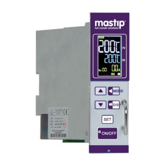
- Page 1 Hot-Runner Temperature Controller with METICOM TM20 module User Guide Ver. 1.01...
-
Page 2: Warranty
Never allow the fan outlets on the unit become blocked, this is where the system's cooling airflow exits. If this area of the mainframe becomes cluttered and insufficient airflow or the system maybe damaged. Page | 1 © Copyright Mastip Technology Limited. Information subject to alteration. V3.53 www.mastip.com... -
Page 3: General Description
WARNING: Before applying power, make sure all international and local electrical codes have been followed and all safety precautions are taken. IMPORTANT: For mold wiring and heater connection information, refer to mold connector wiring diagram. Page | 2 © Copyright Mastip Technology Limited. Information subject to alteration. V3.53 www.mastip.com... -
Page 4: Back Panel Wiring
Temperature Controller METICOM TM20 Module 4. BACK PANEL WIRING Page | 3 © Copyright Mastip Technology Limited. Information subject to alteration. V3.53 www.mastip.com... -
Page 5: Typical System
Temperature Controller METICOM TM20 Module 5. TYPICAL SYSTEM WIRING DIAGRAM Page | 4 © Copyright Mastip Technology Limited. Information subject to alteration. V3.53 www.mastip.com... - Page 6 Combination Power & Thermocouple Connector (16 or 24 Pin) Separate Power & Thermocouple Connector (16 or 24 Pin) Separate Power & Thermocouple Connector (25 Pin) Page | 5 © Copyright Mastip Technology Limited. Information subject to alteration. V3.53 www.mastip.com...
-
Page 7: Module Operation
◆ Control accuracy: ±0.25%F.S. ◆ Control output device: Triac ◆ Load capability: 15A, 50W~1650W(110V),100W~3600W(240V) ◆ Operating temperature: 0℃~55℃(32℉~131℉) ◆ Operating humidity: 10~80%, non-condensing ◆ Storage temperature: -20℃~70℃ (-4℉~158℉) Page | 6 © Copyright Mastip Technology Limited. Information subject to alteration. V3.53 www.mastip.com... - Page 8 ◆ Heater fault alarm ◆ Heating invalid alarm ◆ High alarm of ambient temperature ◆ High limit of load current ◆ High limit of output percentage Page | 7 © Copyright Mastip Technology Limited. Information subject to alteration. V3.53 www.mastip.com...
- Page 9 * Selected by parameter “LCK”. ⒀ ↑key: Used to increase setting number. ⒁ ↓key: Used to decrease setting number. ⒂ SET key: Used for parameter Calling up/Registration. Page | 8 © Copyright Mastip Technology Limited. Information subject to alteration. V3.53 www.mastip.com...
-
Page 10: Operating Modes
DISP key). The controller uses a PID algorithm to determine the required output power to hold the present temperature value equal Page | 9 © Copyright Mastip Technology Limited. Information subject to alteration. V3.53 www.mastip.com... - Page 11 For the next 15 seconds (or until you press the MODE key again, whichever is sooner), 20% is added to the controller output (100% output or parameter Pub limited maximum). Normal indicator flashes. Page | 10 © Copyright Mastip Technology Limited. Information subject to alteration. V3.53 www.mastip.com...
- Page 12 If manual mode when power off, same as nSL=3 when power on. 9) rES: initialize controller. 0: Off. 1: All parameters are reset to factory setting after power-on. Page | 11 © Copyright Mastip Technology Limited. Information subject to alteration. V3.53 www.mastip.com...
- Page 13 3) Adr: communication ID and zone number displayed / output setting when high deviation alarm (ALM-H). 0~99: ID / Zone number displayed as 0~99; and in case ALM-H active, output relay will not be active (cut off output). Page | 12 © Copyright Mastip Technology Limited. Information subject to alteration. V3.53 www.mastip.com...
- Page 14 Note: The manual output percent initial value is 0 (when nSL=0) or equal to parameter “A-n” (when nSL=1). 13) Poi: present temperature display resolution. 0: 1℃/℉ 1: 0.1℃/℉ 11. Default of parameters Parameter Default Parameter Default Parameter Default Parameter Default Page | 13 © Copyright Mastip Technology Limited. Information subject to alteration. V3.53 www.mastip.com...
-
Page 15: Alarm Messages
Check the power ------ Temperature Normal Over voltage H H H supply. Thermocouple is Check the ------ Temperature Normal H E R out of its position thermocouple. Page | 14 © Copyright Mastip Technology Limited. Information subject to alteration. V3.53 www.mastip.com...
Need help?
Do you have a question about the TM20 and is the answer not in the manual?
Questions and answers