Advertisement
Table of Contents
- 1 Table of Contents
- 2 Specifications
- 3 Accessories
- 4 Case Features
- 5 Side and Front View
- 6 I/O and Buttons
- 7 Side Panel Removal
- 8 Front Bezel Removal
- 9 Top Panel Removal
- 10 Motherboard Installation
- 11 Graphics Card Installation
- 12 SSD Installation
- 13 PSU Installation
- 14 Top Panel I/O Connection
- 15 Control Board Connection
- 16 General Information
- Download this manual
Advertisement
Table of Contents

Related Manuals for MSI MAG Series


Summary of Contents for MSI MAG Series
- Page 1 MAG Series PC Case MAG PANO M100R PZ MAG PANO M100R PZ WHITE User Guide...
-
Page 2: Table Of Contents
Contents Specifications .....................3 Accessories ......................5 Case Features ....................6 Side and Front View ...................7 I/O and Buttons ....................8 Side Panel Removal ...................9 Front Bezel Removal ..................10 Top Panel Removal ..................11 Motherboard Installation .................12 Graphics Card Installation ................13 SSD Installation ....................14 PSU Installation ....................15 Top Panel I/O Connection ................16 Control Board Connection ................17 General Information ..................19... -
Page 3: Specifications
Specifications Basic Information Case Type Mid Tower Dimensions (DxWxH) 440 x 235 x 405 mm Micro-ATX*, Mini-ITX Supported Motherboard Sizes * Supports Micro-ATX back-connect motherboard Cooling Fan Support 3 x 120mm or 2 x 140mm Front 1 x 120mm or 1 x 140mm Rear (Pre-installed 1 x 120mm ARGB fan) 3 x 120mm... - Page 4 I/O Ports and Buttons 1 x USB 3.2 Gen1 Type-A USB Ports 1 x USB 3.2 Gen 2x2 Type-C Audio Ports 1 x Audio/Microphone combo jack 1 x Power button Buttons 1 x LED switch button Chassis Clearances Maximum CPU Cooler Height 175 mm Maximum GPU Length 390 mm...
-
Page 5: Accessories
Accessories Item Name / Q’ty Used for Cable ties Cable management Screw M3 5mm Motherboard / SSD Screw #6-32 5mm 3.5” HDD Screw #6-32 6mm Securing PSU / PCIe Card Stand-off #6-32 6.5mm Motherboard Stud Screw #6-32 30mm Securing fans on the PSU shroud Stand-off Mounting Tool Securing stand-off... -
Page 6: Case Features
Case Features... -
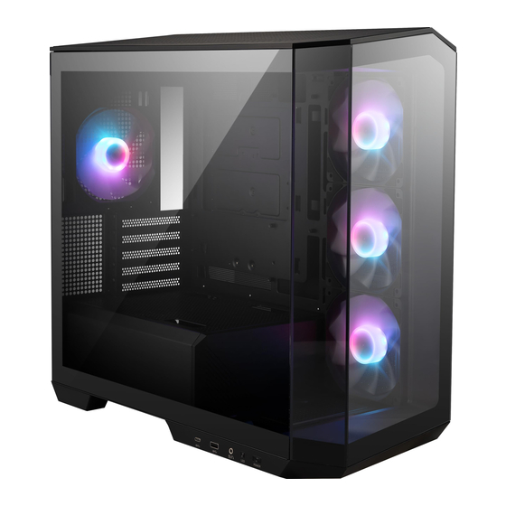
Page 7: Side And Front View
Side and Front View 440mm 235mm... -
Page 8: I/O And Buttons
I/O and Buttons Item Description USB 3.2 Gen 2 2x2 Type-C port USB 3.2 Gen 1 Type-A port Audio/Microphone combo jack LED switch button Power button... -
Page 9: Side Panel Removal
Side Panel Removal The side panel is held in place by snap-fit clips... -
Page 10: Front Bezel Removal
Front Bezel Removal Before removing the front bezel, please remove the side panels on both sides and gently pull out the front panel with your hand. -
Page 11: Top Panel Removal
Top Panel Removal... -
Page 12: Motherboard Installation
Motherboard Installation... -
Page 13: Graphics Card Installation
Graphics Card Installation... -
Page 14: Ssd Installation
SSD Installation... -
Page 15: Psu Installation
PSU Installation... -
Page 16: Top Panel I/O Connection
Top Panel I/O Connection HD AUDIO F_PANEL JUSB JUSB JAUD1 JFP1 (USB 3.2 Gen2) (USB 3.2 Gen1) -
Page 17: Control Board Connection
Control Board Connection LED Switch button ARGB LED Motherboard ARGB connector and Motherboard fan connector Power supply’s SATA connector Addressable RGB LED Strip Connection ARGB extension cable ARGB strip ARGB connector Addressable RGB LED Fan Connection ARGB connector Fan connector ARGB Fan ARGB ARGB... - Page 18 ⚠ IMPORTANT ∙ Please always turn off the power supply and unplug the power cord from the power outlet before installing or removing the ARGB LED Strip/Fan. Supports a maximum of 80 LEDs. Exceeding this limit may result in overheating, ∙...
-
Page 19: General Information
Copyright and Trademarks Notice Copyright © Micro-Star Int’l Co., Ltd. All rights reserved. The MSI logo used is a registered trademark of Micro-Star Int’l Co., Ltd. All other marks and names mentioned may be trademarks of their respective owners. No warranty as to accuracy or completeness is expressed or implied.
Need help?
Do you have a question about the MAG Series and is the answer not in the manual?
Questions and answers
(MSI MAG PANO 100R PZ) I have an extra 2 pin RGB plug and Power connector coming from front of case plugged into the RGB Controller. Came that way with only 3 of the 4 case fans plugged in. I don't understand what these two extra wires are for. And how do I then power the 4th Fan? And my Controller is mounted top not center. Is there a front case Emblem that lights up or something? Not quite sure how to open the front to find where they are coming from. Separate from the front connectors arrays.
The MSI MAG PANO M100R PZ includes a pre-installed 1-to-4 ARGB-PWM control board. The extra 2-pin RGB plug and power connector are used to power the control board and allow lighting control through the LED switch or Mystic Light software.
To connect the 4th fan:
- Use the available port on the 1-to-4 ARGB-PWM control board.
- Connect the fan's 3-pin ARGB and 4-pin PWM connectors to the board.
- The board syncs lighting effects across all connected ARGB fans.
This answer is automatically generated