Table of Contents
Advertisement
Quick Links
Advertisement
Table of Contents

Related Manuals for MCZ GIO' AIR 8 S1


Summary of Contents for MCZ GIO' AIR 8 S1
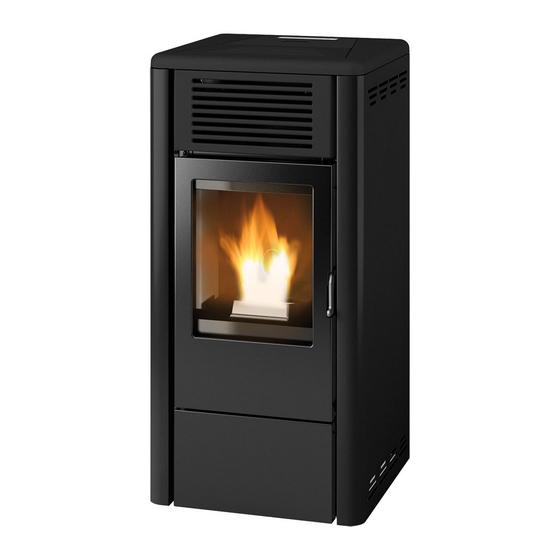
- Page 1 INSTALLATION GUIDE SEALED PELLET STOVE GIO’ AIR 8 S1 Instructions in English...
-
Page 2: Table Of Contents
TABLE OF CONTENTS TABLE OF CONTENTS ....................II INTRODUCTION ......................1 1-WARNINGS AND WARRANTY CONDITIONS ..............2 2-INSTALLATION ......................9 3-DRAWINGS AND TECHNICAL FEATURES ..............18 4-INSTALLATION AND ASSEMBLY ................20 5-CONNECTION TO ADDITIONAL DEVICES ..............27 6-LOADING THE PELLETS ...................28 7-ELECTRICAL CONNECTION..................29 8-FIRST START-UP ....................30 9-CONTROL PANEL ....................32 10-MENU ITEMS AND OPERATION ................33 11-SAFETY DEVICES ....................42... -
Page 3: Introduction
REVISIONS TO THE PUBLICATION The content of this manual is strictly technical and the property of MCZ Group Spa. No part of this manual may be translated into other languages and/or adapted and/or reproduced, even in part, in other mechanical or electronic forms, photocopies, recordings or other, without the prior written authorisation from MCZ Group Spa. -
Page 4: 1-Warnings And Warranty Conditions
1-WARNINGS AND WARRANTY CONDITIONS SAFETY PRECAUTIONS • Installation, electrical connection, function test and maintenance must only be carried out by authorised and qualified personnel. • Install the product in accordance with all local and national legislation and regulations in force in the region or state. • Only use the fuel recommended by the manufacturer. - Page 5 1-WARNINGS AND WARRANTY CONDITIONS • Do not put linen on the product to dry. Any drying racks or the like must be kept at a safe distance from the product. Fire hazard. • All liability for improper use of the product is entirely borne by the user and relieves the Manufacturer from any civil and criminal liability.
- Page 6 1-WARNINGS AND WARRANTY CONDITIONS exposed to weathering. • It is recommended not to remove the feet that support the product in order to guarantee adequate insulation, especially if the flooring is made of flammable materials. • In the event of a malfunction of the ignition system, do not force it to light by using flammable materials.
- Page 7 1-WARNINGS AND WARRANTY CONDITIONS INFORMATION: Please contact the retailer or qualified personnel authorised by the company to resolve a problem. • You must only use the fuel specified by the manufacturer. • When the product is switched on for the first time it is normal for it to emit smoke due to the paint heating for the first time. Therefore make sure the room in which it is installed is well ventilated.
- Page 8 1-WARNINGS AND WARRANTY CONDITIONS and therefore the product is used correctly. The replacement of the entire system or the repair of one of its components does not extend the warranty period, and the original expiry date remains unchanged. The warranty covers the replacement or free repair of parts recognised as being faulty at source due to manufacturing defects. In the event of a fault, to benefit from the warranty, the customer must keep the warranty certificate and provide it with the document given at the time of purchase to the Service Centre.
- Page 9 1-WARNINGS AND WARRANTY CONDITIONS SPARE PARTS In the event of a malfunction, consult the retailer who will forward the call to the Technical Assistance Department. Only use original spare parts. The retailer or service centre can provide all necessary information regarding spare parts. We do not recommend waiting for the parts to get worn out before having them replaced.
- Page 10 1-WARNINGS AND WARRANTY CONDITIONS Our solid bio-combustible products, (hereinafter called “Products”) are designed and manufactured in compliance with one of the following European standard harmonised to Regulation (UE) no. 305/2011 for construction products: EN 14785: “Residential space heating appliances fired by wood pellets” EN 13240: “Roomheaters fired by solid fuel.”...
-
Page 11: 2-Installation
2-INSTALLATION The instructions in this chapter refer explicitly to the Italian installation regulation UNI 10683. In any case, always observe the regulations in force in the country of installation. PELLETS Wood pellets are manufactured by hot-extruding compressed sawdust which is produced during the working of natural dried wood. The compactness of the material is guaranteed by the lignin contained in the wood itself and allows pellets to be produced without glue or binders. - Page 12 2-INSTALLATION FOREWORD The installation position must be chosen according to the room, smoke extraction system and flue. Check with local authorities whether there are any restrictive regulations in force regarding the combustion air inlet, the smoke outlet system, the flue or the chimneypot. The manufacturer declines all responsibility in the event of installations that do not comply with the laws in force, incorrect room air exchange, electrical connection non-compliant with the standards and inappropriate use of the appliance.
- Page 13 2-INSTALLATION FOREWORD The Chimney Flue chapter has been drawn up with reference to the provisions of European Standards (EN13384 - EN1443 - EN1856 - EN1457). The chapter provides indications for installing an efficient and correct flue but is under no circumstances to substitute the regulations in force, which the qualified technician must be in possession of.
- Page 14 2-INSTALLATION TECHNICAL CHARACTERISTICS Have the efficiency of the flue checked by an authorised technician. The flue must be sealed against flue gasses, in a vertical direction without narrowing, be made with materials impermeable to smoke, condensation, thermally insulated and suitable to resist normal mechanical stress over time (we recommend fireplaces made of A/316 or refractory material with insulated round section double chamber).
- Page 15 2-INSTALLATION ROOF AT 60° ROOF AT 45° 45° 60° A = MIN. 2.60 metres A = MIN. 2.00 metres FIGURE 6 FIGURE 5 B = DISTANCE > 1.20 metres B = DISTANCE > 1.30 metres C = DISTANCE < 1.20 metres C = DISTANCE <...
- Page 16 2-INSTALLATION MAINTENANCE The flue must be kept clean, since the deposit of soot or unburned oils reduces the cross-section reducing the draft and thus compromising the efficient operation of the stove and, if large build-ups accumulate, can catch fire. The flue and chimneypot must be cleaned and checked by a qualified chimney sweep at least once a year.
- Page 17 2-INSTALLATION EXTERNAL AIR INLET It is mandatory to provide an adequate external air inlet that supplies the combustion air required for the product to work properly. The flow of air between the outside and the installation room may be direct, through an inlet in an external wall of the room; or indirect, via air intake from adjoining rooms and connecting permanently with the installation room (see Figure 9 b).
- Page 18 2-INSTALLATION In order to fully enhance the sealed features and heating performance of this Oyster appliance, and thus to avoid fitting a free air intake in the room, It is recommended to connect the air required for combustion directly to the external air intake through 060 mm piping with a maximum length of 3 linear metres, using the suitable “j”...
- Page 19 2-INSTALLATION EXAMPLES OF CORRECT INSTALLATION 1. Installation of Ø120mm flue with hole for the passage of the pipe increased by: minimum 100mm around the pipe if next to non flammable parts such as cement, brick, etc.; or minimum 300mm around the pipe (or as required by rating plate) if next to flammable parts such as wood etc.
-
Page 20: 3-Drawings And Technical Features
3-DRAWINGS AND TECHNICAL FEATURES DRAWINGS AND CHARACTERISTICS GIO’ AIR 8 S1 STOVE DIMENSIONS Ø80 Ø48 Ø80 Ø48... - Page 21 3-DRAWINGS AND TECHNICAL FEATURES TECHNICAL CHARACTERISTICS GIO’ AIR 8 S1 Energy Efficiency Class Nominal output power 8.0 kW (6880 kcal/h) Minimum power output 2.5 kW (2150 kcal/h) Efficiency at Max 90.4% Efficiency at Min 92.0% Temperature of exhaust smoke at Max 196 °C Temperature of exhaust smoke at Min 103 °C...
-
Page 22: 4-Installation And Assembly
4-INSTALLATION AND ASSEMBLY PREPARATION AND UNPACKING Remove all the parts of the packaging (polystyrene, wood, plastic). All packaging materials can be reused for similar use or disposed of as urban solid waste, in accordance with current regulations. After having removed the packaging make sure the product is intact. Handle the product with suitable means paying attention to the applicable safety regulations in force. - Page 23 4-INSTALLATION AND ASSEMBLY Therefore, the end user is responsible for product storage, disposal or possible recycling in compliance with the relative applicable laws in force. Do not store the stove unit or its cladding without their packaging. Position the stove and connect it to the flue pipe. Remove the plastic clamp securing the top to the stove’s frame. If the stove needs to be connected to an outlet pipe which goes through the rear wall (to connect to the flue), take utmost care to make sure that the joint is not forced.
- Page 24 4-INSTALLATION AND ASSEMBLY DISASSEMBLING THE TOP Lift the tank cover “B” and remove the top “A”. To remove the top “A”, simply lift it off its rubber supports and put it in a safe place until it is to be used again.
- Page 25 4-INSTALLATION AND ASSEMBLY REMOVING THE SIDE PANEL The stove is delivered fully assembled; if you need to remove the side panels for technical service or cleaning, proceed as follows: • raise the cover of the pellet tank “B” • remove the top “A” •...
- Page 26 4-INSTALLATION AND ASSEMBLY DISASSEMBLING THE FRONT PANELS After removing the side panels “C” and “D”, proceed as follows: • Undo the four screws “v” and remove the upper front panel “E” • Undo the two screws “z” and remove the lower front panel “F” Put the panels “E”...
- Page 27 4-INSTALLATION AND ASSEMBLY ACCESS TO THE ELECTRONIC BOARD The electronics board “m” is on the right side (handle side). If you need to access the board, you must remove the back side panel as explained above. ACCESS TO THE GEARMOTOR To access the gearmotor, you must remove the four screws “x”...
- Page 28 4-INSTALLATION AND ASSEMBLY OPENING THE DOOR OF THE FIREBOX To open the firebox door, fit the cold handle “F” into its hole in the handle, and pull it outwards. Attention! The firebox door must be closed properly for the stove to work correctly. Only open the doors when the stove is switched off and cold.
-
Page 29: 5-Connection To Additional Devices
5-CONNECTION TO ADDITIONAL DEVICES INSTALLING THE MODEM / PROGRAMMABLE THERMOSTAT (OPTIONAL) To install the thermostat and the mode, refer to their instruction manuals. The modem mounts to the stove’s back panel with adhesive velcro, while the programmable thermostat’s receiver “U” mounts onto the provided holes. -
Page 30: 6-Loading The Pellets
6-LOADING THE PELLETS LOADING THE PELLETS The fuel is loaded from the top of the stove by lifting the hatch “B” with the included cold handle “G”. Pour the pellets in slowly so that they are deposited at the bottom of the hopper. If loading pellets when the stove is running, open the door of the tank using the stove mitten that comes with the stove itself. -
Page 31: 7-Electrical Connection
7-ELECTRICAL CONNECTION ELECTRICAL CONNECTION First connect the power cable to the back of the stove and then to a wall socket. It is recommended to disconnect the power cable when the stove is not used. The cable must never come into contact with the smoke exhaust pipe or any other part of the stove. STOVE POWER SUPPLY Connect the power cable to the back of the stove and then to a wall socket. -
Page 32: 8-First Start-Up
8-FIRST START-UP PRECAUTIONS BEFORE START-UP GENERAL PRECAUTIONS Remove any objects that may burn from the brazier (manual, various adhesive labels or any polystyrene). Check that the brazier is positioned correctly and rests properly on the base. The first start-up may not be successful as the feed screw is empty and does not always manage to load the required amount of pellets in time to light the flame. - Page 33 8-FIRST START-UP depending on the heat stored in the structure, determined by the duration and the operating regime of the product throughout the day. When the internal temperature drops below the set thresholds, the fans for hot air and exhaust fume extraction will automatically switch off.
-
Page 34: 9-Control Panel
9-CONTROL PANEL 1. Stove switch-on/switch-off 5. Decrease set temperature / programming functions. 2. Scrolling down through the programming menu 6. Increase set temperature / programming functions. 3. Menu 7. Display. 4. Scrolling up the programming menu... -
Page 35: 10-Menu Items And Operation
10-MENU ITEMS AND OPERATION MAIN MENU Press key 3 (menu) to access. The options accessed are: • Date and Time • Timer • Sleep (only when stove is on) • Settings • Info Date and time configuration Configure the time and date as follows: •... - Page 36 10-MENU ITEMS AND OPERATION EXAMPLES OF PROGRAMMING 08:00 12:00 11:00 14:00 Stove on between 08:00 and 14:00 08:00 11:00 11:00 14:00 Stove on between 08:00 and 14:00 17:00 24:00 00:00 06:00 Stove on between 17:00 on Monday to 06:00 on Tuesday NOTES ON USE OF THE TIMER •...
- Page 37 10-MENU ITEMS AND OPERATION OPERATING MODE ADJUSTMENTS MENU “Adjustments” menu settings determine the operation mode of the stove. To access the menu, proceed as follows: • Press the - + keys • Scroll with the <> arrows and select “Set Amb. T” or “Set Ventilation T” or “Set Flame” •...
- Page 38 10-MENU ITEMS AND OPERATION SETTINGS MENU The SETTINGS menu is to configure use of the stove: a. Language. b. Cleaning (shown only when stove is off). Auger loading (shown only when stove is off). d. Tones. e. External thermostat (activation). Auto Eco (activation).
- Page 39 10-MENU ITEMS AND OPERATION d - Tones This function is disabled by default. To enable it proceed as follows: • Press the “menu” key. • Use the arrow keys to scroll through and select “Settings” • Press “menu” to confirm. •...
- Page 40 10-MENU ITEMS AND OPERATION h - Pellet Recipe This function is for adapting the stove to the type of pellet in use. As there are many types of pellet available on the market, operation of the stove can vary considerably according to the quality of the fuel. When the pellets clog up the brazier due to excess loading of fuel or when the flames are high even at low power, or when the flames are low, it is possible to decrease/increase the amount of pellets in the brazier: Available values:...
- Page 41 10-MENU ITEMS AND OPERATION • Use the arrow keys to scroll through and select ‘’Component test’’ • Press “menu” to confirm. • Use the + - keys to select the test to be carried out. • Press ‘’menu’’ to confirm and ‘’ e sc’’ to exit. k - Chimney sweeper function (for maintenance operators only) - This function can only be activated when the stove is on and power is supplied, and it forces operation of the boiler at the parameters P5, with the ventilator (if present) in V5.
- Page 42 10-MENU ITEMS AND OPERATION EXTERNAL THERMOSTAT CONNECTION (optional) The room thermostat is not included with the stove and must be installed by a qualified technician. CAUTION! The electrical wires must not come into contact with the hot parts of the stove. AMB.
- Page 43 10-MENU ITEMS AND OPERATION Remote control (accessory - NOT SUPPLIED) LEGEND OF BUTTONS 1. Increase temperature set-point 4. Temperature/power switch and vice versa. 2.Decrease temperature set-point 5/6. Set power and ventilation 3. ON/OFF PLEASE NOTE Adjusting the temperature with the remote control has no effect if the external thermostat has been selected. Attention! Before using, remove the protection from the battery.
-
Page 44: 11-Safety Devices
11-SAFETY DEVICES SAFETY DEVICES The product is fitted with the following safety devices PRESSURE SWITCH Monitors pressure in the smoke duct. It is designed to shut down the pellet feed screw in the event of an obstructed flue or significant back-pressure (from the wind). -
Page 45: 12-Alarms
12-ALARMS ALARM SIGNALLING When a condition occurs other than the one expected for regular operation of the stove, an alarm is triggered. The reason for the alarm is given on the control panel. The sound signal is not enabled for alarms A01-A02 in order not to disturb the user when there is an absence of pellets in the night tank. - Page 46 12-ALARMS NORMAL SHUTDOWN (on the panel: OFF with flashing flame symbol) When the shutdown key is pressed, or when there is an alarm signal, the stove enters the thermal extinguishing phase which involves automatic execution of the following phases. • Stop pellet loading •...
- Page 47 12-ALARMS In the event that alarm A05 is triggered often, please note that: Smoke pressure switch intervention Check for chimney obstructions / door open Fuel loading hatch Close the hatch. Lower the fuel level in the tank. Safety devices alarm Open stove door Close the door you must check some points to verify the cause of the problem and possibly act on some adjustments and/or safety devices to restore the...
- Page 48 12-ALARMS If all the above checks are negative, it is likely that the depression inside the stove drops due to poor performance of the flue, especially when the machine is operating at minimum speed for a long time. In this case it is possible to make small adjustments that allow you to increase the operating speed of the smoke fan to increase the depression inside the product, or make it less sensitive to the intervention of the pressure switch by changing its position mechanically.
-
Page 49: 13-Recommendations For Safe Use
13-RECOMMENDATIONS FOR SAFE USE ONLY CORRECT INSTALLATION AND APPROPRIATE MAINTENANCE AND CLEANING OF THE APPLIANCE CAN GUARANTEE CORRECT OPERATION AND SAFE USE OF THE PRODUCT. We would like to inform you that we are aware of cases of malfunctioning of domestic pellet-fuelled heating products, mainly due to incorrect installation and use, as well as inadequate maintenance. -
Page 50: 14-Cleaning
14-CLEANING EXAMPLE OF A CLEAN BRAZIER EXAMPLE OF A DIRTY BRAZIER Only by properly servicing and cleaning the product is it possible to ensure its safety and correct operation. ATTENTION! All the cleaning operations of all parts must be performed with the product completely cold and the plug disconnected. - Page 51 14-CLEANING For the brazier to be cleaned properly, remove it from its housing completely and thoroughly clean all the holes and the grate on the bottom. If good quality pellets are used, you will normally only need to use a brush to restore the optimal operating conditions of the component.
- Page 52 14-CLEANING PERIODIC CLEANING PERFORMED BY A QUALIFIED TECHNICIAN CLEANING THE HEAT EXCHANGER Half-way through the winter season, but especially at the end, the compartment through which the exhaust smoke passes will need to be cleaned. This cleaning process is mandatory in order to facilitate the general removal of all combustion residue, before it becomes very difficult to remove it due to the humidity compacting it over time.
- Page 53 14-CLEANING CLEANING THE EXCHANGER CLEANING THE UPPER COMPARTMENT Clean the upper exchanger when the stove is cold and without cladding. After removing the cap for lower cleaning “N” (see previous paragraph), use a stiff rod or a bottle brush to scrape the firebox walls (see arrow) so that the ash falls into the lower compartment. Then remove the upper Calorite plate “H”;...
- Page 54 14-CLEANING Use a stiff rod or a bottle brush to scrape the firebox walls (see arrow - at the right and left of the firebox respectively) so that the ash falls into the lower compartment. Use a vacuum cleaner nozzle to vacuum up any remaining ash and dust on the exchanger (see arrow).
- Page 55 14-CLEANING In the upper section, too, remove the front panel “E” (see the instructions in the dedicated paragraphs) and insert the nozzle of the vacuum cleaner to remove any deposits of dust. Then thoroughly clean the lower exchanger, replace any gaskets if needed, and reassemble. Technical Dept.
- Page 56 14-CLEANING CLEANING THE SMOKE DUCT AND GENERAL CHECKS Clean the smoke extractor system, especially around the “T” joints, elbows and any horizontal sections of the smoke duct. For information on periodically cleaning the flue, contact a skilled chimney sweep. Check the seal of the ceramic fibre gaskets on the door of the stove. If necessary, order new replacement gaskets from the retailer or contact an authorised service centre to carry out the operation.
- Page 57 14-CLEANING SHUTDOWN (end of season) At the end of each season, before switching the product off, it is recommended to remove all the pellets from the tank with a vacuum cleaner with a long pipe. We recommend removing the unused pellet from the tank because it can retain humidity. Disconnect any combustion air ducting that can lead humidity inside the combustion chamber but, above all, ask the specialised technician to refresh the paint inside the combustion chamber with the special silicone spray paints (available at any store or CAT) during the necessary annual end of season scheduled maintenance operations.
-
Page 58: 15-Troubleshooting
15-TROUBLESHOOTING ATTENTION! All repairs must only be carried out by a specialised technician, with the product switched off and the plug disconnected. ANOMALY POSSIBLE CAUSES SOLUTIONS The pellets are not fed into The pellet hopper is empty Fill the hopper with pellets. the combustion chamber. - Page 59 15-TROUBLESHOOTING ANOMALY POSSIBLE CAUSES SOLUTIONS Pellets accumulate in the brazier, the Insufficient combustion air. Clean the brazier and check that all the glass of the door gets dirty and the holes are clear. Perform a general cleaning flame is weak. of the combustion chamber and the smoke duct.
- Page 60 15-TROUBLESHOOTING ANOMALY POSSIBLE CAUSES SOLUTIONS Incorrect combustion adjustment. Check recipe. No increase in temperature with stove in operation. Set flame 1 setting (level too low) Increase power from the settings menu. Poor pellet quality. Using pellets from the producer.
-
Page 61: 16-Circuit Board
16-CIRCUIT BOARD AMB. H2O +TC- DISPLAY TERM. ENCODER FUMI OPT. +5V GND ENC LIVE ELECTRICAL CABLES SERIAL DISCONNECT THE POW- ER SUPPLY CABLE 230V BEFORE CARRYING OUT ANY OPERATIONS ON THE ELECTRICAL BOARDS ACC. SIC DEP. FUMI SCA COC. WIRING KEY 1. - Page 64 Via La Croce n°8 33074 Vigonovo di Fontanafredda (PN) – ITALY Telephone: +39 0434/599599 r.a. Fax: +39 0434/599598 Internet: www.mcz.it e-mail: info.red@mcz.it 8901825001 REV 0 11/09/2020...
Need help?
Do you have a question about the GIO' AIR 8 S1 and is the answer not in the manual?
Questions and answers