Table of Contents
Advertisement
Quick Links
No: IS-0685– rev. 2 5/23
CC-STAT
Country of Origin: Made in China
•
One thermostat for all applications - works with single-
stage, heat pump, multi-stage and control of humidifier and
dehumidifier systems
•
On-board relative humidity sensor configurable to control
humidifier and dehumidifier
•
Communicates with InFusion controller, Vantage
touchscreens, and mobile apps for remote operation and
feedback
Description
Dimensions
Model
Power Draw Maximum
Power Draw Typical
Power Input
Maximum Load Per Terminal
Maximum Load All Terminals
DC Power
Compatible Systems
Terminal Designations
Rated Output Current
Control Range
Communicating Thermostat
Installation Instructions
The CC-STAT Vantage Communicating Thermostat provides the comfort and energy
efficiency your customers expect with easy installation and full InFusion integration.
The CC-STAT may function as a stand-alone HVAC thermostat; however, the system
user will experience enhanced and simplified control when the CC-STAT is integrated
with the InFusion system. LCD interfaces and touchscreens provide the interface and
the CC-STAT, installed near the HVAC system, provides the control.
When combined with the Thermostat Interface Station, this multi-function thermostat
is compatible with most residential HVAC systems, including single stage, heat pump,
multi-stage and control of humidifier and dehumidifier systems.
FEATURES AND OPERATION OVERVIEW
SPECIFICATIONS
4.9375" H x 6" W x 1.3125" D (125.4mm H x 98.4mm W x 49.2mm D)
CC-STAT
86.4 mA rms – This value is with 24 VAC input voltage and backlight ON
21.6 mA rms – This value is with 24 VAC input voltage and backlight OFF
18-30 Vac (24VAC nominal), 50/60Hz
1 Amp
2.5 Amp
3.0 Volts DC (2 "AA" Alkaline batteries included
Standard gas, oil, electric, single stage/heat pump/multi-stage
Rc, R, W, Y, G, C, S1, S2, O, B, L, W2, Y2, T1, T2, C, B, O, Y, Y2, G, RC, R, W2, WL, S2,
S1, T1, T2, A-, B-, A+, B+, RSA, RSB
0.001 A to 1 A continuous per output with up to 5 A surge (half cycle)
45º to 99ºF (7º to 32ºC)
1
OVERVIEW
•
Direct connection of outdoor or indoor sensors
•
Allows for temporary override of Vantage System without
altering initial programming
•
Automatic set points controlled through the Vantage System
•
Backward compatible
Specification
Advertisement
Table of Contents

Subscribe to Our Youtube Channel
Related Manuals for LEGRAND VANTAGE CC-STAT


Summary of Contents for LEGRAND VANTAGE CC-STAT
- Page 1 Communicating Thermostat Installation Instructions No: IS-0685– rev. 2 5/23 CC-STAT Country of Origin: Made in China OVERVIEW The CC-STAT Vantage Communicating Thermostat provides the comfort and energy efficiency your customers expect with easy installation and full InFusion integration. The CC-STAT may function as a stand-alone HVAC thermostat; however, the system user will experience enhanced and simplified control when the CC-STAT is integrated with the InFusion system.
-
Page 2: Specification
SPECIFICATIONS (continued) Description Specification Display Range 32º to 99ºF (0º to 40ºC) Accuracy ± 1ºF (± .5ºC) Storage Temperature -30º to 140ºF (-34.4º to 60ºC) Operating Humidity 5% to 90% relative humidity Operating Ambient Temperature 32º to 120ºF (0º to 48.9ºC) Shipping Temperature Range -30º... -
Page 3: Installation
SECTION ONE INSTALLATION No: IS-0685 – Rev. 2... -
Page 4: Warning / Caution
INSTALLATION OVERVIEW WARNING - CAUTION! 1. 120 volts may cause serious injury from electrical shock. Disconnect electrical power to the HVAC system before starting installation. This system is a low-voltage system. 2. Improper installation may cause serious injury from electrical shock. HVAC systems must be installed by a qualified contractor in accordance with NEC Standards and applicable local and state codes. -
Page 5: Outdoor Temperature Sensor (Optional)
CC-STAT OPTIONAL SUPPORT MODULES AND SENSORS These support modules can be added when remote temperature or humidity sensor values are needed. Support modules can also be used for sensor averaging in large areas (see Maximum Wiring Distances below). Support modules must be used in Control Mode, see instructions shipped with module. -
Page 6: Remote Temperature Sensors (Optional)
REMOTE TEMPERATURE SENSORS (OPTIONAL) A remote indoor temperature sensor can be used if the thermostat is to be mounted in a concealed location. A Vantage flush mount sensor, part number FLUSHSENSOR, or surface mount sensor, part number SENSOR-SMT, can be attached to the T1 and T2 terminals and mounted in a recommended area. - Page 7 TEMPERATURE AVERAGING (continued) Connect multiple thermostat sensors for temperature averaging. Only 4 or 9 sensor configurations are allowed for averaging. Only wire multiple sensors as shown. NINE SENSOR TEMPERATURE AVERAGING – SCHEMATIC 9 Sensors (see additional information shipped with sensor) NOTE: Temperature averaging using the CC-TEMPSUP support module’s built-in temperature sensor allows averaging 2, 3, or 4 sensors.
- Page 8 THERMOSTAT TERMINAL WIRING DIAGRAM B+ A+ B- A- C Y2 G RC RH W2 W R S2 S1 T1 T2 RSB RSA B+ A+ B- A- C Y2 G RC RH W2 W R S2 S1 T1 T2 RSB RSA WIRE SPECIFICATIONS THERMOSTAT WIRING TERMINAL KEY •...
-
Page 9: Single Transformer
CONVENTIONAL HEAT / COOL WIRING DIAGRAM SINGLE TRANSFORMER - (Use Jumper Wire From RC to RH) HVAC SECTION THERMOSTAT IS POWERED FROM HVAC TRANSFORMER - OR - THERMOSTAT IS POWERED FROM EXTERNAL 24VAC TRANSFORMER COMMUNICATION SUPPORT TERMINALS MODULE B+ A+ B- A- C Y2 G RC RH W2 W R S2 S1 T1 T2 RSB RSA THERMOSTAT SECTION... - Page 10 CONVENTIONAL HEAT / COOL WIRING DIAGRAM TWO TRANSFORMERS - (Use Jumper Wire From RC to RH) HVAC SECTION THERMOSTAT IS POWERED FROM THE HEAT OR COOL SYSTEM’S TRANSFORMER - OR - THERMOSTAT IS POWERED FROM EXTERNAL 24VAC TRANSFORMER COMMUNICATION SUPPORT TERMINALS MODULE B+ A+ B- A- C...
-
Page 11: Heat Pump Wiring Diagram
HEAT PUMP WIRING DIAGRAM SINGLE TRANSFORMER - (Use Jumper Wire) HEAT PUMP SECTION THERMOSTAT IS POWERED FROM THE HEAT PUMP TRANSFORMER - OR - THERMOSTAT IS POWERED FROM EXTERNAL 24VAC TRANSFORMER COMMUNICATION SUPPORT TERMINALS MODULE B+ A+ B- A- C Y2 G RC RH W2 W R S2 S1 T1 T2 RSB RSA THERMOSTAT SECTION... - Page 12 HEAT PUMP WIRING DIAGRAM TWO TRANSFORMERS - (Remove Jumper Wire) HEAT PUMP SECTION THERMOSTAT IS POWERED FROM THE HEAT PUMP TRANSFORMER COOL - OR - THERMOSTAT IS POWERED FROM EXTERNAL 24VAC TRANSFORMER COMMUNICATION SUPPORT TERMINALS MODULE B+ A+ B- A- C Y2 G RC RH W2 W R S2 S1 T1 T2 RSB RSA THERMOSTAT SECTION...
-
Page 13: Dry Contact
HUMIDISTAT WIRING DIAGRAM DRY CONTACT THERMOSTAT IS POWERED FROM EQUIPMENT OR 24VAC TRANS. COMMUNICATION SUPPORT TERMINALS MODULE B+ A+ B- A- C Y2 G RC RH W2 W R S2 S1 T1 T2 RSB RSA POWERED CONTACT THERMOSTAT IS POWERED FROM EQUIPMENT OR 24VAC TRANS. -
Page 14: Vantage Integration
VANTAGE INTEGRATION CC-STAT-WL-KIT / CC-STAT-RL-KIT SETUP AND CONFIGURATION CC-WLINT, WireLink™ or the CC-RLINT, RadioLink® thermostat interface stations provide bidirectional communication between the Vantage control system and the HVAC system. Any button or time control using InFusion Design Center can be programmed to change Setpoints, Mode, Fan, Network Override (formerly Occupied/Unoccupied mode), etc., on any thermostat. -
Page 15: Wiring To Cc-Wlint Or Cc-Rlint For Hvac Or Humidity Control
MOUNTING THE CC-WLINT OR CC-RLINT CONFIGURATION When the CC-WLINT or CC-RLINT is properly connected and CONFIGURE BUTTON powered the status LED will have a two blink pattern for the WireLink model or a three blink pattern for the RadioLink model which typically means it is not configured. -
Page 16: Design Center Integration Overview
DESIGN CENTER INTEGRATION OVERVIEW THERMOSTAT SETUP WITH INFUSION In Area View select the floor and room for the thermostat. Click on Vantage Objects in the Object Explorer and expand Stations, WireLink or Stations, RadioLink and double click on the thermostat station to add it to the room. In the Object Editor name the station and make sure it is on the correct station bus. -
Page 17: Setup And Testing
SECTION TWO SETUP and TESTING No: IS-0685 – Rev. 2... - Page 18 EQUIPMENT TYPE SELECTION SWITCH (SWS1) This thermostat has the option of being used in heat pump or heat/cool systems. Switch SW1 located on the back of the thermostat’s face to select the proper operation. This setting can also be verified (but not set) in the Installer Setup menu system settings under Equipment Type.
-
Page 19: Installer System Settings Table
INSTALLER SYSTEM SETTINGS TABLE The following table is the list of the settings and their details. Default settings are shown in bold. Some settings are only available to thermostats set to heat pump or humidistat mode. System Setting Description Factory Default Setting (Bold) and Setting Range 00. - Page 20 System Setting Description Factory Default Setting (Bold) and Setting Range 19. THIRD STAGE 3rd Stage differential 1°F (0.5°C) DIFFERENTIAL 1°F to 9°F (0.5C to 4.5°C) 20. FOURTH STAGE 4th Stage differential 1°F (0.5°C) DIFFERENTIAL 1°F to 9°F (0.5C to 4.5°C) 21.
- Page 21 INSTALLER SYSTEM SETTINGS TABLE (continued) System Setting Description Factory Default Setting (Bold) and Setting Range 40. LOCKOUT TYPE Screen lockout level (Override lockout by holding [MENU] for 7 seconds PARTIAL FULL 41. MODE LOCKOUT System mode lockout setting DISABLE ENABLE 42.
-
Page 22: System Test Menu
SYSTEM TEST MENU The system test menu is used to test a system after installation. The outputs of the thermostat or humidistat can be manually activated to test their function. The instructions below show how to enter the test mode and turn outputs on and off. HOW TO ENTER THE SYSTEM TEST MENU: Press [MODE] to set system to OFF. -
Page 23: System Test Tables
SYSTEM TEST TABLES TEST 60: HEATING EQUIPMENT TEST BUTTON EQUIPMENT STAGES HEAT TYPE PRESS TYPE Heat Cool 1st UP Electric Press Heat Pump Heat Cool 2nd UP Electric Press Heat Pump TEST 60: COOLING EQUIPMENT TEST BUTTON EQUIPMENT STAGES PRESS TYPE Heat Cool 1st UP... -
Page 24: Quick Reference To Controls And Display
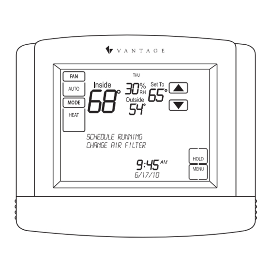
SECTION THREE QUICK REFERENCE TO CONTROLS and DISPLAY No: IS-0685 – Rev. 2... - Page 25 HOME SCREEN DIAGRAM ROOM RELATIVE HUMIDITY OUTDOOR TEMPERATURE TEMPERATURE SETTING CURRENT DAY ROOM TEMPERATURE TEMPERATURE ADJUSTMENT FAN MODE BUTTON FAN MODE SETTING SYSTEM MODE BUTTON HOLD BUTTON (In programmable mode SYSTEM MODE SETTING Heating sets or clears hold) EQUIPMENT STATUS NETWORK OVERRIDE (In non-programmable mode) MESSAGE CENTER...
- Page 26 HUMIDISTAT The Model CC-STAT has the option of being configured as a humidistat* that can control a humidifier and dehumidifier. NOTE: The CC-STAT is set to operate as a humidistat through the installer setup menu. ROOM RELATIVE HUMIDITY SETPOINT CURRENT DAY ROOM RELATIVE HUMIDITY HUMIDIFIER ADJUSTMENT...
- Page 27 SECTION FOUR THERMOSTAT FEATURES and TROUBLESHOOTING No: IS-0685 – Rev. 2...
-
Page 28: Troubleshooting
THERMOSTAT FEATURES • Large touch screen with adjustable backlight • Easy to use temperature control can override program schedule at any time • Message center provides feedback and instructions • Progressive recovery ensures proper temperature at the • Thermostat can be removed from the wall for easy start of a program event programming (batteries must be installed) •... - Page 29 TROUBLESHOOTING: HEAT PUMP ISSUES COOL AIR IN HEAT MODE, OR WARM AIR IN COOL MODE • Check wiring at the terminal block to confirm the reversing valve is connected to the proper terminal. O is active in cooling and B is active in heating.
- Page 30 No. IS-0685 – rev. 2 5/23 © Copyright 2023 Legrand All Rights Reserved. 800.555.9891 © Copyright 2023 Tous droits réservés Legrand. www.legrand.us/vantage © Copyright 2023Legrand Todos los derechos reservados.
Need help?
Do you have a question about the VANTAGE CC-STAT and is the answer not in the manual?
Questions and answers