Table of Contents
Advertisement
Quick Links
No: 341319 6/21
Catalog Number(s):
WZ3TSTATH
Country of Origin: Made in China
READ & SAVE THESE INSTRUCTIONS!
WARNING:
To reduce the risk of fire, electric shock, or product damage, do
not expose this apparatus to rain, moisture, immersion, dripping or
splashing. No objects filled with liquids, such as vases, should be
placed on this apparatus.
CAUTION:
• Do not obstruct the unit's ventilation openings with curtains,
fabrics, and similar items.
• Do not place sources of open flames such as candles on the
unit.
• Do not place in areas of direct heating or cooling vents
• 5.2 GHz band is restricted to indoor use only.
Purpose of Control: Operating Control
TYPE 1 or TYPE 2 Action: TYPE 1.C
External Pollution Situation: Pollution Degree 2
Rated Impulse Voltage: 330V
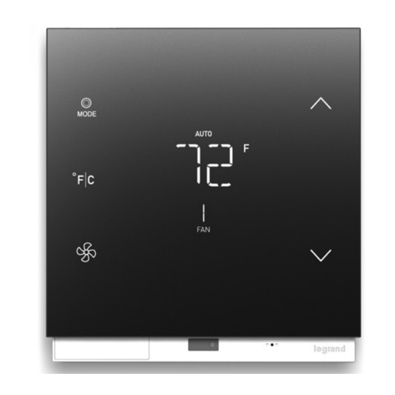
1. System overview
The WZ3TSTATH is an integrated smart thermostat and room gateway that
enables new user experiences for today's smart hotel rooms. It is intended
to be installed by trained installers and requires integration into an Enseo
hospitality system.
OFF
AUTO
MODE
CELCIUS
FARENHEIT
FAN
AUTO
3
2
1
1.1. Indicators
Temperature – Indicates the current room temperature. Display can be in
Fahrenheit or Celsius. The temperature decimal is used in Celsius mode
System Off – Indicates that the HVAC system is off
Auto – Indicates that the HVAC is in auto mode. Note: Auto and Off are
exclusive of each other
Set Temperature – Indicates set point temperature for thermostat
Room Temperature – Indicates current room temperature
Fan Speed – Indicates fan speed. Indicators are speeds 1-3 and Auto.
Pass & Seymour
WZ3TSTATH Thermostat Installation Manual
Installation Instructions
For the latest version of this document please visit:
https://www.legrand.us/wiring-devices/smart-lighting/smart-hospitality/smart-thermostat-with-zigbee-3.0-hub/p/wz3tstathbk
REGULATORY INFORMATION
FCC NOTICE: This device complies with Part 15 of the FCC
rules. Operation is subject lo the following two conditions; (1) this
device nay not cause harmful interference, and (2) this device
must accept any interference received, including interference that
may cause undesirable operation.
This equipment has been tested and found lo comply with the
limits for a Class B digital device, pursuant to Part 15 of the
FCC Rules. These limits are designed to provide reasonable
protection against harmful interference in a residential installation.
This equipment generates, uses, and can radiate radio
frequency energy and, if not installed and used in accordance
with the instruction, may cause harmful interference to radio
communications. However, there is no guarantee that interference
will not occur in a particular installation.
If this equipment does cause harmful interference lo radio or
television reception, which can be determined by turning the
equipment off and on, the user is encouraged to try to correct the
interference by one or more of the following measures:
• Reorient or relocate the receiving antenna
• Increase the separation between the equipment and receiver
• Connect the equipment into an outlet on a circuit different from
that to which the receiver is connected
• Consult the dealer or an experienced radio/TV technician for
help
NOTE: Any changes or modifications to this device that are not
expressly approved by the manufacturer will void the warranty and
the user's authority to operate the equipment.
FCC ID: 2AU5DWZ3TSTAT
The distance between user and device should be no less than
20cm.
IC Notice: This device contains licence-exempt transmitter(s)/
receiver(s) that comply with Innovation, Science and Economic
Development Canada's licence-exempt RSS(s). Operation is
subject to the following two conditions:
THERMOSTAT OVERVIEW
1.2. End User Input & Operations
Power/Modes
Item
Power /
Modes
INCREASE
TEMPERATURE
F/C
DECREASE
TEMPERATURE
Fan
Increase
Decrease
®
(1) This device may not cause interference.
(2) This device must accept any interference, including
interference that may cause undesired operation of the device.
L'émetteur/récepteur exempt de licence contenu dans le présent appareil est
conforme aux CNR d'Innovation, Sciences et Développement économique
Canada applicables aux appareils radio exempts de licence. L'exploitation est
autorisée aux deux conditions suivantes :
1) L'appareil ne doit pas produire de brouillage;
2) L'appareil doit accepter tout brouillage radioélectrique subi, même si le
brouillage est susceptible d'en compromettre le fonctionnement.
IC: 25764-WZ3TSTAT
HVIN: WZ3TSTATH
IMPORTANT SAFETY INSTRUCTIONS
Read these operating instructions carefully before using the
unit. Follow the safety instructions on the unit and the applicable
safety instructions listed below. Keep these instructions for future
reference.
1. Read these instructions.
2. Keep these instructions.
3. Heed all warnings.
4. Follow the instructions.
5. Do not use this apparatus in or near water.
6. Clean only with a dry cloth.
7. Do not block any ventilation openings. Install in accordance
with the manufacturer's instructions.
8. Do not install near any heat sources such as radiators, heat
registers, stoves, or other apparatus (including amplifiers) that
produce heat.
9. Use only attachments/accessories specified by the
manufacturer.
10. Refer all servicing to qualified service personnel. Servicing is
required when the apparatus has been damaged in any way,
such as power plug damage, liquid spills or objects falling onto
the apparatus. Also, if the apparatus has been exposed to rain
or moisture, does not operate normally, or has been dropped.
Description
1. When system powerup, it will first enter sleep mode.
2. Proximity triggers the system into wakeup mode.
3. Press to power on the HVAC system into Auto mode.
1. Press once, select the C, Celsius mode.
2. Press again, toggle to F, Fahrenheit mode.
3. When user change to C or F, the corresponding room
temperature and set point temperature needs to be updated
4. The F/C button only active at wakeup mode
1. Fan speed. Press to toggle between Auto->1->2->3 if
HVAC system is at auto mode.
Press increase shall increase the set point temperature of
Auto Mode. Each step is 1 degree in F or 0.5 degree in C
mode)
When the user touches the temperature increase button, the
display will switch to the current set point temperature. It can be
modified using the increase/decrease buttons. After 3 seconds of
inactivity the system will set the last set point temperature.
Press decrease shall decrease the set point temperature of Auto
Mode. Each step is 1 degree in F or 0.5 degree in C mode)
When the user touches the temperature decrease button, the
display will switch to the current set point temperature.
It can be modified using the increase/decrease buttons. After
3 seconds of inactivity the system will set the last set point
temperature.
Default
Off
F
Auto
68F or
20C
68F or
20C
Advertisement
Table of Contents

Related Manuals for LEGRAND Pass & Seymour WZ3TSTATH


Summary of Contents for LEGRAND Pass & Seymour WZ3TSTATH
- Page 1 Installation Instructions Catalog Number(s): WZ3TSTATH For the latest version of this document please visit: https://www.legrand.us/wiring-devices/smart-lighting/smart-hospitality/smart-thermostat-with-zigbee-3.0-hub/p/wz3tstathbk Country of Origin: Made in China REGULATORY INFORMATION (1) This device may not cause interference. FCC NOTICE: This device complies with Part 15 of the FCC (2) This device must accept any interference, including rules.
- Page 2 2. INSTALLATION Header 3 The thermostat is typically mounted to an industry standard double gang junction box or trim ring about 5 feet above the floor. Example Legrand TER DAM R 24VAC part numbers are shown in the chart below.
- Page 3 2.3.3. Harness 3 - RS485 PN WATSTATH301 2.3.4. Harness 4 – Damper PN WATSTATH401 Pin Number Function Color Pin Number Function Color RS-485 A (-) Black Reserved no connection RS-485 B (+) TER_Dam R 24 VAC Green TER Dam No Normally Open White TER Dam No Normally Closed Black...
- Page 4 2.3.5 Wiring Diagrams (continued) 2.3.5.3 Diagram 3 – HpO Single Stage Heat 24VAC – Maestro App Type 3F HpO-1SH 2.3.5.4 Diagram 4 – HpB Second Stage Heat 24VAC – Maestro App Type 2F HpB-2SH 2.3.5.5 Diagram 5 – HpO Second Stage Heat 24VAC – Maestro App Type 2F HpO-2SH...
- Page 5 2.3.5 Wiring Diagrams (continued) 2.3.5.6 Diagram 6 – VFD & Heat/Cool – Maestro App Type VFD HC 2.3.5.7 Diagram 7 – 3 Fan&Cool – Maestro App Type 3F C 2.3.5.8 Diagram 8 – 2 Pipe Cool with Electric Heat – Maestro App Type 3F C+EH...
- Page 6 2.3.5 Wiring Diagrams (continued) 2.3.5.9 Diagram 9 – VRF – Maestro App Type VRF 2.3.5.10 Diagram 10 – Damper...
- Page 7 3. INITIAL SETUP 3.1.5. Change Set-point Heat Set-point heat is set by pressing the mode button until the indicator above Before going through initial setup, please make certain that the thermostat the temperature readout says Heat. Using the Up and down arrows modify is properly mounted to the wall.
- Page 8 Un-rented / Un-Occupied temperature high limits (no PMS Present 80 F User interface mode configuration for manual heat / cool with no auto User Interface mode configuration for manual heat / cool 800-223-4185 341319 – 6/21 1.877.BY.LEGRAND www.legrand.us © Copyright 2021 Legrand All Rights Reserved. www.legrand.ca...
Need help?
Do you have a question about the Pass & Seymour WZ3TSTATH and is the answer not in the manual?
Questions and answers