Table of Contents
Advertisement
Quick Links
Advertisement
Table of Contents

Subscribe to Our Youtube Channel
Related Manuals for Extreme Networks 7720


Summary of Contents for Extreme Networks 7720
- Page 1 Extreme 7720 Hardware Installation Guide 9037387-00 Rev. AC December 2023...
- Page 2 Extreme Networks, Inc. reserves the right to make changes in specifications and other information contained in this document and its website without prior notice. The reader should in all cases consult representatives of Extreme Networks to determine whether any such changes have been made.
-
Page 3: Table Of Contents
Preface.............................. 7 Audience........................................7 Text Conventions....................................7 Documentation and Training..............................9 Help and Support....................................9 Subscribe to Product Announcements.........................10 Send Feedback....................................10 Extreme 7720 Series Overview....................12 Management......................................12 Cooling........................................12 Power Supplies....................................13 Stacking ........................................13 Secure Boot......................................13 Operating Temperatures................................14 Feature Licensing....................................14 Extreme 7720 Series Switch Features..........................14... - Page 4 Log In for the First Time on Fabric Engine........................65 Remove and Replace Components..................67 Replace Internal Power Supplies............................67 Replace an 800 W Internal AC Power Supply....................67 Replace an 800 W Internal DC Power Supply....................70 Extreme 7720 Hardware Installation Guide...
- Page 5 RJ-45 Management Port LEDs..............................78 QSFP28 Port LEDs...................................78 800 W AC Power Supply LEDs...............................79 800 W DC Power Supply LEDs..............................79 Technical Specifications......................81 7720 Series Technical Specifications..........................81 External Interfaces.................................. 81 Weights and Dimensions of Accessories......................82 Acoustic Noise and Fan Speed.............................. 83 Acoustic Noise...................................83 Fan Tray and Speed Variation............................
- Page 6 BSMI statement (Taiwan)................................98 Canadian requirements................................98 China CCC statement................................... 99 Australia (RCM)....................................99 Federal Communications Commission (FCC) Notice..................99 Germany statement..................................100 KCC statement (Republic of Korea)..........................100 Japan (VCCI Class A)..................................100 Japan power cord ..................................101 Index.............................. 102 Extreme 7720 Hardware Installation Guide...
-
Page 7: Preface
Extreme Networks devices. Note If the information in an installation note or release note shipped with your Extreme Networks equipment differs from the information in this guide, follow the installation or release note. Text Conventions Unless otherwise noted, information in this document applies to all supported environments for the products in question. - Page 8 New information. In a PDF, this is searchable text. Table 3: Command syntax Convention Description bold text Bold text indicates command names, keywords, and command options. italic text Italic text indicates variable content. Extreme 7720 Hardware Installation Guide...
-
Page 9: Documentation And Training
Extreme Optics Compatibility Other resources such as white papers, data sheets, and case studies Extreme Networks offers product training courses, both online and in person, as well as specialized certifications. For details, visit www.extremenetworks.com/education/. Help and Support If you require assistance, contact Extreme Networks using one of the following... -
Page 10: Subscribe To Product Announcements
1 (408) 579 2826. For the support phone number in your country, visit: www.extremenetworks.com/support/contact Before contacting Extreme Networks for technical support, have the following information ready: • Your Extreme Networks service contract number, or serial numbers for all involved Extreme Networks products • A description of the failure •... - Page 11 Preface Send Feedback Provide the publication title, part number, and as much detail as possible, including the topic heading and page number if applicable, as well as your suggestions for improvement. Extreme 7720 Hardware Installation Guide...
-
Page 12: Extreme 7720 Series Overview
Management An RJ45 serial console port on the front panel of the 7720 Series switch enables you to connect a terminal and perform local management. An Ethernet management port can be used to connect the system to an out-of-band management network for administration. -
Page 13: Power Supplies
Power supplies are ordered separately for the base model 7720-32C. Power supplies are included with other models. For more information about the power supplies used in the 7720 Series switches, see Power Supplies for Use with Your Switch on page 18. -
Page 14: Operating Temperatures
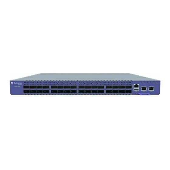
0°C (32°F) to 35°C (95°F) above 1800 m (6000 ft), up to 3000m (10,000 ft) Feature Licensing The 7720 Series switches support Unified Licensing, so that you can use them with multiple operating systems. There are two methods of acquiring feature licenses: manual or through ExtremeCloud™... - Page 15 • 1 10/100/1000BASE-T out-of-band management port • 1 Type A USB storage port Figure 1: 7720-32C Switch Front Panel 1 = 40/100Gbps QSFP28 ports 3 = Type A USB storage port 2 = RJ-45 serial console port 4 = 10/100/1000BASE-T OOB management ports...
-
Page 16: Port Partitioning
One 1 Gb port with the 10506 QSA adaptor (both Switch Engine and Fabric Engine) Note: Port 28 cannot be partitioned and is 40/100G capable only. Switch Engine 32.4 For information about configuring partitioned ports, see the Command Reference Guide Extreme 7720 Hardware Installation Guide... -
Page 17: Secure Boot
Boot Image Verified • Boot Image Verification Failed Secure Boot Troubleshooting When there is a secure boot validation failure, the switch is booted to a recovery stage or halts. Contact GTAC for assistance with recovering the switch. Extreme 7720 Hardware Installation Guide... -
Page 18: Power Supplies For Use With Your Switch
Power supplies are ordered separately for base model 7720-32C. Power supplies are included with other models. -
Page 19: 800 W Ac Power Supply
800W AC power supply - back-to-front airflow (part no. XN-ACPWR-800W-R) Note AC power input cords are not provided with AC power supplies. You can order an appropriate cord from Extreme Networks or from your local supplier. The power cord must meet the requirements listed in Power Cord Requirements for AC-Powered Switches and AC Power Supplies on page 88. -
Page 20: Build Stacks
SummitStack cables. All connections between stack ports must be directly between switches. A stacking connection cannot pass through a third device, for example a Virtual Port Extender or an LRM/MACsec Adapter. Extreme 7720 Hardware Installation Guide... -
Page 21: Build Basic Stacks
Native stacking can be configured using Native-400 utilizing QSFP28 optics or Native-400-Alternative-Configuration using long range AOC optics. When planning and building your stack, be sure to follow port compatibility and cabling recommendations as described in this chapter. Extreme 7720 Hardware Installation Guide... -
Page 22: Summitstack Topologies
“primary-capable,” meaning they can become a stack primary in case the initial backup switch fails. SummitStack Topologies Figure 4 presents a graphical representation of a stack and some of the terms that describe stack conditions. Extreme 7720 Hardware Installation Guide... - Page 23 The result forms a physical ring connection. This topology is highly recommended for normal operation. Figure 5 represents a maximal ring topology of eight active nodes. Extreme 7720 Hardware Installation Guide...
- Page 24 Connect your stack nodes in a ring topology, not a daisy-chain topology, for normal operation. Figure 7, the nodes delineated as the active topology are operating in a daisy-chain configuration, even though there is physically a ring connection in the stack. Extreme 7720 Hardware Installation Guide...
-
Page 25: Summitstack Terms
Table 5: List of Stacking Terms Term Description Stackable switch An Extreme Networks switch that provides two stacking ports and can participate in a stack. Stacking port A physical interface of a stackable switch that is used to allow the connection of a stacking link. Stacking ports are point-to- point links that are dedicated for the purpose of forming a stack. - Page 26 Thus, the active topology is a set of physically contiguous active nodes within a stack topology. Extreme 7720 Hardware Installation Guide...
- Page 27 VLAN or trunk group. They can be used for Layer 2 and 3 forwarding of user data traffic, for mirroring, or other features you can configure. Data ports are different from stacking ports. Extreme 7720 Hardware Installation Guide...
- Page 28 The choice to run Easy Setup is offered when you run the enable stacking {node-address node-address} command and the essential stacking parameters are unconfigured or inconsistent. It can also be invoked directly by running the configure stacking easy-setup command. Extreme 7720 Hardware Installation Guide...
-
Page 29: Plan To Create Your Stack
Switch Engine application synchronization traffic is localized to a single stack link. • On the primary node, connect the Ethernet management port to your management network. Extreme 7720 Hardware Installation Guide... -
Page 30: Recommendations For Configuring Stacks
If the primary-capable stackable switches have different purchased license levels, you might need to configure license level restrictions on some nodes before Switch Engine 32.4 User Guide those nodes can join the stack. See the for more information about managing licenses. Extreme 7720 Hardware Installation Guide... -
Page 31: Combine Switches From Different Series
V400-Alternative-configuration (using the long range AOC optics). Both the 7520 Series and the 7720 Series have the same capability in terms of feature scalability and the speed, so either of them can be the primary switch or the backup switch. - Page 32 Each switch model is represented by a rectangle, as shown in the example in the following figure. In this example, stacking ports are represented by ports 31 and 32 on the right side, which are the stacking ports for 7720-32C model. Figure 8: 7720 Switch Shown in the Stacking Tool Select a rectangle to display more information about the switch model and the VIMs (if any) that it can use for stacking.
-
Page 33: Set Up The Physical Stack
Examples of Valid Stacking Configurations The examples in the following sections show various physical stacking arrangements: all switches in a single rack, switches in two adjacent racks, and switches at the tops of several racks in a row. Extreme 7720 Hardware Installation Guide... - Page 34 Slot 4 Stack Port 2 Slot 1 Stack Port 1 Example: Basic Stack with Eight Switches Figure 10 shows cable connections for an 8-node stack using SummitStack 40G cables to connect switches with integrated SummitStack ports. Extreme 7720 Hardware Installation Guide...
- Page 35 Port 2 on one switch is connected to Port 1 on the next connected switch. If the easy setup feature is used to configure the stack parameters, the assigned slot numbers will be as shown in the figure. Extreme 7720 Hardware Installation Guide...
-
Page 36: Connect Your Stack To The Management Network
Ethernet management port. See the Switch Engine User's Guide for the version of Switch Engine you are using, for instructions to perform the software configuration for your stack. Extreme 7720 Hardware Installation Guide... -
Page 37: Site Preparation
1. Meeting site requirements. The physical installation site must meet the following requirements for a safe and successful installation: • Building and electrical code requirements • Environmental, safety, and thermal requirements for the equipment you plan to install Extreme 7720 Hardware Installation Guide... -
Page 38: Operating Environment Requirements
After examining your physical site and verifying that all environment requirements are met, evaluate and compare your existing cable plant with the requirements of the Extreme Networks equipment to determine if you need to install new cables. 3. Meeting power requirements. -
Page 39: Set Up The Wiring Closet
Make sure that your system is easily accessible for installation and service. See Rack Specifications and Recommendations on page 41 for more information. • Use appropriate AC or DC power, power distribution, and grounding for your specific installation. Extreme 7720 Hardware Installation Guide... -
Page 40: Control The Temperature
Consult an electrical contractor for commercial building and wiring specifications. Control the Temperature Extreme Networks equipment generates a significant amount of heat. It is essential that you provide a temperature-controlled environment for both performance and safety. Install the equipment only in a temperature- and humidity-controlled indoor area that is free of airborne materials that can conduct electricity. -
Page 41: Control The Humidity Level
Site Preparation Control the Humidity Level Safeguards are built into all Extreme Networks switches and power supply units to minimize the risk of fire. Table 11: Thermal Shutdown and Restart Behavior Switch Model(s) Behavior All models When internal system temperatures exceed the thermal shutdown temperature limit (typically about 20°C higher than normal system... -
Page 42: Mechanical Recommendations For The Rack
Because building codes vary worldwide, consult an electrical contractor to ensure proper equipment grounding for your specific installation. Provide Adequate Space for the Rack Provide enough space in front of and behind the switch so that you can service it easily. Extreme 7720 Hardware Installation Guide... -
Page 43: Secure The Rack
(61 cm) of space behind the mounted equipment. Extra room on each side is optional. Warning Extreme Networks switches do not have a switch for turning power to the unit on and off. For systems using an AC power supply, power to the switch is disconnected by removing the wall plug from the electrical outlet. -
Page 44: Label Cables And Keep Accurate Records
• Assign a unique identification number to each equipment rack. • Identify all wiring closets by labeling the front panel of your Extreme Networks equipment and other hardware. • Keep accurate and current cable identification records. - Page 45 Fiber optic cable must be handled carefully during installation. Every cable has a minimum bend radius, and fibers will be damaged if the cables are bent too sharply. It is also important not to stretch the cable during installation. Ensure Extreme 7720 Hardware Installation Guide...
- Page 46 Table 12: Cable Distances and Types Standard Media Type MHz•km Maximum Rating Distance (Meters) 1000BASE-SX 50/125 µm multimode fiber (850nm optical window) 50/125 µm multimode fiber 62.5/125 µm multimode fiber 62.5/125 µm multimode fiber Extreme 7720 Hardware Installation Guide...
- Page 47 10/125 µm single-mode fiber – 40,000 (1550nm optical window) 1 Proprietary to Extreme Networks. Connections between two Extreme Networks 1000BASE-LX interfaces that use 10/125 µm single-mode fiber can use a maximum distance of 10,000 meters. Extreme 7720 Hardware Installation Guide...
-
Page 48: Use Rj45 Connector Jackets
0.1" = 1mm actual Better 39.37% : 254% SPG_001 Figure 15: RJ45 Connector Jacket Types Prevent Radio Frequency Interference (RFI) If you use UTP cabling in an installation, take precautions to avoid radio frequency (RF) interference. Extreme 7720 Hardware Installation Guide... -
Page 49: Meet Power Requirements
• In regions that are susceptible to electrical storms, the best practice is to plug your system into a surge suppressor. For detailed power specifications for your equipment, see "Technical Specifications." Extreme 7720 Hardware Installation Guide... -
Page 50: Power Cord Requirements
Most ExtremeSwitching switches do not ship with power cords. Visit www.extremenetworks.com/product/powercords/ for information on selecting and purchasing the correct power cords for use with specific Extreme Networks equipment. The web page provides specifications for power cords in each country so that you can purchase cords locally. -
Page 51: Follow Applicable Industry Standards
UPS transition time is sometimes called UPS transition times vary between UPS models and implementations, but shorter transition times are preferred. For Extreme Networks stacking products, a UPS transition time of 20 milliseconds or less ensures optimum performance and minimizes service interruptions. -
Page 52: Install The Switch
Turn on the Switch on page 61 Connect Network Interface Cables on page 61 Before you attempt to install or remove an Extreme Networks switch, read the precautions in Safety Considerations for Installation on page 53. Extreme Networks switches fit into standard 19-inch equipment racks. -
Page 53: Safety Considerations For Installation
37, and ensure that you have the appropriate people and tools on hand. Installing Extreme Networks switches is easiest when there are two people to maneuver the switch and attach mounting hardware. Provide enough space in front of and behind the switch so that you can service it easily. -
Page 54: Attach The Switch To A Rack Or Cabinet
Attach the Switch to a Rack or Cabinet Install the Switch Attach the Switch to a Rack or Cabinet The 7720 Series switch can be attached to a standard 19-inch equipment rack, in either of the following ways: • Four-post rack, using the mounting kit provided. - Page 55 If you are using the 1U long rack ears (already attached to the inner rail): Ensure that the rack ear is flush with the either the front or the rear panel of the unit and continue to step on page 57. Extreme 7720 Hardware Installation Guide...
- Page 56 If using the 1U or 2U short rack ears, attach one to the side of the device using the #6-32 screws, so that the rack ear is flush with either the front or the rear panel of the device. Figure 19: Front Installation: Attaching a Rack Ear Extreme 7720 Hardware Installation Guide...
- Page 57 Figure 21: Front Installation: Inserting the Device To install the device in the rear of the rack, slide the device into the outer rails in the rear of the rack. Extreme 7720 Hardware Installation Guide...
-
Page 58: Two-Post Rack Mount
1. On one side of the switch, attach one of the short mounting brackets to the device. a. For a front mount, position the bracket over the holes so that the flange (ear) is even with the front of the device, as shown in the figure below: Extreme 7720 Hardware Installation Guide... - Page 59 If the switch comes with installed power supplies, skip to the topic: Turn on the Switch on page 61. If the switch does not have an installed power supply, install one or two power supplies using the instructions in Install Internal Power Supplies on page 60. Extreme 7720 Hardware Installation Guide...
-
Page 60: Install Optional Components
When using the fiber breakout cables, additional 10Gb optics are required. For 7720 Series switches running either Fabric Engine or Switch Engine, interfaces 0/1 through 0/27 and 0/29 through 0/32 support up to 4 10GbE, 4 25GbE, 1 40GbE, or 1 100GbE ports each in breakout mode when using the appropriate optics. -
Page 61: Turn On The Switch
An AC power cord is not included with the AC power supply. You can purchase AC power cords for use in the US and Canada from Extreme Networks or from your local supplier. The cord must meet the requirements listed in... -
Page 62: Activate And Verify The Switch
XIQ at https:// extremecloudiq.com Switch Engine is the default operating system for the 7720 Series switch. If you want to run Fabric Engine, see Change the Switch OS via the Bootloader Menu... - Page 63 For the initial password, simply press [Enter]. When you have successfully logged on to the system, the command line prompt displays the system name (for example, 7720-32C-SwitchEngine#) in its prompt. You are logged in with administrator privileges, which gives you access to all switch functions.
-
Page 64: Configure The Switch's Ip Address For The Management Vlan
Menu" will only wait for 3 seconds before continuing. To change the switch OS if you take no action during the initial boot, see Change the Switch OS via the Startup Menu on page 65. Extreme 7720 Hardware Installation Guide... -
Page 65: Change The Switch Os Via The Startup Menu
Data bits: 8 • Stop bit: 1 2. Press [Enter] one or more times until you see the login prompt. 3. At the login prompt, log in using the default user name rwa. For example: login: rwa Extreme 7720 Hardware Installation Guide... - Page 66 Activate and Verify the Switch When prompted for the password, enter rwa. When you are logged in with the role-based authentical level of rwa, you can configure the login and password values for the other role-based authentication levels. Extreme 7720 Hardware Installation Guide...
-
Page 67: Remove And Replace Components
70. Replace an 800 W Internal AC Power Supply The switches have two bays for hot-swappable power supplies. In a switch with a redundant power configuration, you can replace one power supply without powering Extreme 7720 Hardware Installation Guide... - Page 68 See Figure Figure 26: Removing a 800 W AC Power Supply 6. Carefully slide the power supply all the way into the power supply bay (see Figure 27). Extreme 7720 Hardware Installation Guide...
- Page 69 Always make sure that the source outlet is properly grounded before plugging the AC power cord into the AC power supply. 9. If the power supply is equipped with a power cord retainer, use the retainer to secure the power cord to the power supply. Extreme 7720 Hardware Installation Guide...
-
Page 70: Replace An 800 W Internal Dc Power Supply
6. Carefully slide the power supply all the way into the power supply bay until the latch snaps into place, as shown in Figure Caution Do not slam the power supply into the switch. Extreme 7720 Hardware Installation Guide... - Page 71 3. Position the DC power cable connector so that the wide, flat side is closest to the fan, as shown in Figure 29. The DC power cable connector can only connect to the power supply one way. Extreme 7720 Hardware Installation Guide...
-
Page 72: Replace Fan Modules
Leave the ESD strap permanently connected to the rack, so that the strap is always available when you need to handle ESD-sensitive components. Replace Fan Modules You can replace fan modules as needed while the switch is operating ("hot swapping"). Extreme 7720 Hardware Installation Guide... -
Page 73: Remove The Device From The Rack
1. Disconnect the device from its power source or sources. 2. Remove all cables and transceivers. 3. To remove a device from a four-post rack, do the following: a. Push the disconnect latch to release the device after it is fully extended. Extreme 7720 Hardware Installation Guide... - Page 74 You can leave the slider assemblies in place. If you want to remove them, continue with the next step. d. On one of the slider assemblies, push the rear clamp until it separates from the rear rack post. Extreme 7720 Hardware Installation Guide...
-
Page 75: Remove The Switch From A Two-Post Rack
1. Unscrew the mounting brackets from the rack while carefully supporting the weight of the device. 2. Tilt the device so that the brackets are clear of the rack posts, and carefully lift it out of the rack. Extreme 7720 Hardware Installation Guide... - Page 76 If the device cannot be tilted (because other equipment is mounted directly above and below), remove one or two mounting brackets from the device and then slide the device out. If you plan to use the device again later, store it with the mounting brackets attached. Extreme 7720 Hardware Installation Guide...
-
Page 77: Monitor The Switch
Either the PSU or fan or both are faulty, not present, or the system has not loaded properly CPU power is off Steady green Normal operation (Power) Blinking green System in reset Unit not operational Extreme 7720 Hardware Installation Guide... -
Page 78: Management Port Leds
Label or Type Color/State Meaning PSU1, PSU2 Steady green PSU is installed and providing power (Power Supplies) Steady amber PSU is installed but input power is disconnected or unit fault detected PSU is not installed Extreme 7720 Hardware Installation Guide... -
Page 79: 800 W Ac Power Supply Leds
AC input OK (Green) Good AC input fail 800 W DC Power Supply LEDs The following table describes the meanings of the LEDs on the 800 W DC power supplies (part number XN-DCPWR-800W-F or XN-DCPWR-800W-R). Extreme 7720 Hardware Installation Guide... - Page 80 Amber No PSU fault OUT OK DC output Good On (solid) DC output OK (Green) Off or Blinking DC output fail IN OK DC input Good "IN DC input OK (Green) OK" DC input fail Extreme 7720 Hardware Installation Guide...
-
Page 81: Technical Specifications
Front-Back and Back-Front airflow options Fan Tray 6 fan modules, support one fan redundancy Front-Back and Back-Front airflow options Dimensions 17.3in W/22.44in D/1.7in H (44.0cm/57.0cm/4.3cm) Weight 16.3 lb (7.4 kg) no PSU/19.9 lb (9.0 kg) with two PSUs Extreme 7720 Hardware Installation Guide... -
Page 82: Weights And Dimensions Of Accessories
(24.80 in - 35.43 in) XN-2P-RKMT299 - Two-post rack 2.8 kg (6.17 lb) Height: 4.44 cm (1.75 in) mount kit (ordered separately) Width: 2.0 cm (0.79 in) Length: 67.93 cm - 93.24 cm (26.76 in - 36.73 in) Extreme 7720 Hardware Installation Guide... -
Page 83: Acoustic Noise And Fan Speed
Technical Specifications Acoustic Noise and Fan Speed Acoustic Noise and Fan Speed Acoustic Noise The following table includes acoustic specifications of the Extreme 7720 Series switches. Switch Model Bystander Sound Pressure (at Declared Sound Power (at 27°C) 27°C) 7720-32C (AC/DC PSU with 45 dB(A) 6.9 bels... -
Page 84: Cpu, Memory Specifications
CPU, Memory Specifications Technical Specifications CPU, Memory Specifications The following table includes CPU and memory specifications for the Extreme 7720 Series switches. 2.2 GHz CPU 16 GB memory, 128 GB SSD 4GB eMMC Flash Memory 32MB buffer for ASIC Mean Time Between Failures The following table includes mean time between failures (MTBF) information for the Extreme 7720 Series switches. -
Page 85: Power Consumption
Technical Specifications Power Consumption Power Consumption The following table includes power consumption information for the 7720 Series switches. Operating Mode Test Conditions Power Consumption Traffic Port Packet Dual Dual Single Duty Load Status Length Power: Power: Power: (Bytes) PSU1 PSU2... -
Page 86: Environmental Operating Conditions
CDRH Letter of Approval (US FDA Approval) European ITE EN 60950-1 2nd Edition EN62368-1 EN 60825-1 Class 1 (Lasers Safety) 2014/35/EU Low Voltage Directive International ITE CB Report & Certificate per IEC 60950-1 CB Report & Certificate IEC 62368-1 Extreme 7720 Hardware Installation Guide... -
Page 87: Emi/Emc Standards
IEC/EN61000-4-11 Power Dips & Interruptions, >30%, 25 periods, Criteria C Country Specific VCCI Class A (Japan Emissions) ACMA RCM (Australia Emissions) CQC Mark (China) KCC Mark, EMC Approval (Korea) BSMI (Taiwan) Anatel (Brazil) NoM (Mexico) EAC (Russia, Belarus, Kazakhstan) NRCS (South Africa) TEC (India) Extreme 7720 Hardware Installation Guide... -
Page 88: Ieee 802.3 Media Access Standards
RXD (receive data) TXD (transmit data) DTR (data terminal ready) GND (ground) DSR (data set ready) RTS (request to send) CTS (clear to send) Figure 34 shows the pinouts for a 9-pin to 25-pin (RS-232) null-modem cable. Extreme 7720 Hardware Installation Guide... - Page 89 9-pin to 9-pin (PC-AT) null-modem serial cable. Figure 35: PC-AT Serial Null-modem Cable Pinouts Table 19 shows the pinouts for the RJ45 console port on the Extreme Networks switches. Table 19: RJ45 Console Port on Switch...
- Page 90 Table 20: Pinouts for an RJ45 to DB-9 Adapter Signal RJ45 Pin DB-9 Pin CTS (clear to send) DTR (data carrier detect) TXD (transmit data) GND (ground) GND (ground) RXD (receive data) DSR (data set ready) RTS (request to send) Extreme 7720 Hardware Installation Guide...
-
Page 91: Safety Information
Only trained and qualified service personnel (as defined in IEC 60950-1 and AS/NZS 3260) should install, replace, or perform service to Extreme Networks switches and their components. Qualified personnel have read all related installation manuals, have the... -
Page 92: General Safety Precautions
Make sure that your power supplies meet the site DC power or AC power requirements of all the network equipment. • Racks for Extreme Networks equipment must be permanently attached to the floor. Failure to stabilize the rack can cause the rack to tip over when the equipment is removed for servicing. -
Page 93: Maintenance Safety
Fiber Optic Ports and Optical Safety The following safety warnings apply to all optical devices used in Extreme Networks equipment that are removable or directly installed in an I/O module or chassis system. Such devices include but are not limited to gigabit interface converters (GBICs), small form factor pluggable (SFP) modules (or mini-GBICs), QSFP+ modules, XENPAK transceivers, and XFP laser optic modules. -
Page 94: Cable Routing For Lan Systems
Cable Routing for LAN Systems Extreme Networks equipment meets the requirements for LAN system equipment. LAN systems are designed for intra-building installations; that is, cable runs between devices must be in the same building as the connected units, except under the conditions listed in the next paragraph. -
Page 95: Select Power Supply Cords
When you install DC power supplies or connect DC power: • Extreme Networks DC power supplies do not have switches for turning the unit on and off. Make sure that the DC circuit is de-energized before connecting or disconnecting the DC power cord at the DC input power socket. -
Page 96: Battery Notice
Il y a risque d’explosion si la pile est remplacée par un type de pile incorrect. Éliminez les piles usées en conformité aux règlements locaux d'élimination des piles. Battery Warning - Taiwan Extreme 7720 Hardware Installation Guide... -
Page 97: Regulatory Information
European Council directives, laws, and standards: • Electromagnetic Compatibility (EMC) Directive 2014/30/EU • Low Voltage Directive (LVD) 2014/35/EU • EN 55032/EN 55024 (European Immunity Requirements) EN61000-3-2/JEIDA (European and Japanese Harmonics Spec) ◦ EN61000-3-3 ◦ Extreme 7720 Hardware Installation Guide... -
Page 98: Emc Warnings
Canadian requirements This Class A digital apparatus meets all requirements of the Canadian Interference- Causing Equipment Regulations, ICES-003 Class A. Cet appareil numérique de la classe A est conforme à la norme NMB-003 du Canada. Extreme 7720 Hardware Installation Guide... -
Page 99: China Ccc Statement
Federal Communications Commission (FCC) Notice This device complies with Part 15 of the FCC rules. Operation is subject to the following two conditions: (1) this device may not cause harmful interference, and (2) this Extreme 7720 Hardware Installation Guide... -
Page 100: Germany Statement
This is a Class A product based on the standard of the VCCI Council. If this equipment is used in a domestic environment, radio interference may occur, in which case the user may be required to take corrective actions. Extreme 7720 Hardware Installation Guide... -
Page 101: Japan Power Cord
Regulatory Information Japan power cord Japan power cord English translation of above statement ATTENTION: Never use the power cord packed with your equipment for other products. Extreme 7720 Hardware Installation Guide... -
Page 102: Index
Extreme 12–14 brackets, for mounting in rack 73, 75 for stacked configurations 36 building codes 38 on switch 88 Building Industry Consulting Service International. settings 62 see BICSI control path 26 conventions notice icons 7 Extreme 7720 Hardware Installation Guide... - Page 103 Index (continued) conventions Extreme 7720 Series switches text 7 features 14 cooling 72 Extreme Stacking Tool 31 cords requirements 88 selecting 95 Fabric Engine initial login 65 failover 28 daisy chain topology 24 data port 27 airflow 72 DB-9 console connector pinouts 88...
- Page 104 Index IP settings pinouts configuring 64 DB-9 console connector 88 null-modem cable 88 planning site 37 jackets plenum-rated cable 44 RJ45 connector 48 , see optical transceivers pluggable transceivers ports console port settings 62 for stacked configurations 36 labeling cables 44 management 62 LEDs native stacking 21...
- Page 105 Index (continued) radio frequency interference (RFI) stacking patch panel installation 44 priority 22 preventing 48 recommendations 29, 30 redundancy redundancy 22 in a stack 22 ring topology 23 regulatory information 97 single-rack 34 removing slot number 22 fan module 72 stack number indicator 22 from rack 73, 75 terminology 25...
- Page 106 Index (continued) UPS (uninterruptible power supply) transition time 51 UTP cable bend radius 44 category 5 44 discharge ESD 44 preventing RFI 48 VLAN configuring 64 warnings 7 web app SummitStack 31 wiring closet electrostatic discharge (ESD) 41 floor coverings 39 grounding 39 humidity 41 rack, securing 43...
Need help?
Do you have a question about the 7720 and is the answer not in the manual?
Questions and answers