
Related Manuals for Ikan OTTICA OTT-CONTROLLER-V2


Summary of Contents for Ikan OTTICA OTT-CONTROLLER-V2
- Page 1 Manual OTT-CONTROLLER-V2 OTTICA IP PTZ Camera Controller www.ikancorp.com sales@ikancorp.com - 1 -...
-
Page 2: Table Of Contents
Table of Contents Parameters & Specs Communication & Control Interface Camera Control or Operation Control Signal Format Power Supply and Consumption Physical & Others Description of Button & Knob Function Interface Function and Connection Diagrams Upgrade Interface RS422/RS485 Interface RS232 Interface LAN Interface DC Power Supply Interface System Menu Operation Instructions... -
Page 3: Parameters & Specs
Parameters & Specs Communication & Control Interface RS422/RS485 Interface Phoenix Contact 4 pin 3.81mm Terminal RS232C Interface DB9 Male Interface LAN Interface RJ45 Female Interface Power Supply JEITA type4 Female Interface Upgrade Online Micro USB Female Interface Camera Control or Operation Supports up to Control Cameras Communication Protocol VISCA, PELCO P/D, UDP... -
Page 4: Control Signal Format
Parameters & Specs (continued) Control Signal Format Baud Rate 2400bps, 4800bps, 9600bps, 19200bps, 38400bps Date Bits 8 Bit Stop Bit 1 Bit Parity Bit None Internet Protocol UDP / VISCA OVER IP Power Supply and Consumption Rated Voltage DC 12V / Power Over Ethernet (Optional) Rated Current 0.3A max Max Power Consumption... -
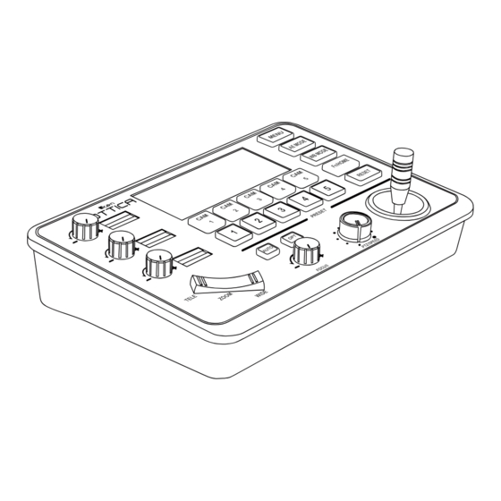
Page 5: Description Of Button & Knob Function
Description of Button & Knob Function MENU AE MODE WB MODE Fn/HOME RESET PRESET AUTO TELE ZOOM WIDE FOCUS PTZ/SPEED 1. This Rotation Knob is used to adjust the Camera Exposure Parameter or Red Gain Value. Turning the knob to the right increases the value, while turning it to the left decreases the value. - Page 6 8. Focus Function Zoom. When the Backlight of the [AUTO] button is lit up, it indicates that the current focusing mode is automatic. When the Backlight of the [AUTO] button is turned off, it means that the current focus mode has been changed to manual. Users can press this button to switch between the modes.
- Page 7 After pressing the [RESET] button, the green backlight will start to flash. Press the preset number to be cleared (e.g., [RESET] + [number key 1]). At this time, the flashing of the green light on the [RESET] key stops, and “Reset Preset 1” is displayed on the screen, indicating that preset 1 has been cleared.
- Page 8 Exposure Mode Knob 1 Knob 2 Knob 3 Auto NOT USED NOT USED Exposure Compensation Manual Shutter Iris Gain Shutter Priority Shutter NOT USED Exposure Compensation Iris Priority Iris NOT USED Exposure Compensation Brightness Priority Iris Gain Exposure Compensation Table 1 [ WB MODE KEY ] This key is used to change the White Balance mode of the camera.
- Page 9 - 9 -...
- Page 10 - 10 -...
-
Page 11: Interface Function And Connection Diagrams
Interface Function and Connection Diagrams 1. Upgrade Interface The interface is used for upgrading the hardware of the keyboard using a laptop. It involves a direct connection between the PC and the keyboard using a Micro USB cable. The upgrade is performed using our upgrade tools software. 2. -
Page 12: Rs232 Interface
3. RS232 Interface This interface is used for connecting the camera through RS232. Please refer to the detailed connection diagram shown in the following pictures. 4. LAN Interface The LAN interface is used for connecting to a network switch or other devices. -
Page 13: Dc Power Supply Interface
Connect multiple cameras using the LAN interface. The detailed connection diagram is shown below. When connecting multiple cameras, you need to set the IP address of each camera separately using a computer. 5. DC Power Supply Interface This interface is the power supply interface. You can directly connect it to the power adapter. -
Page 14: System Menu Operation Instructions
System Menu Operation Instructions System Menu Operation & Explanation 1. Long-press [ MENU ] for 3 seconds to turn on the Keyboard system Menu. 2. The joystick moves up and down: controls the system menu cursor to move up and down or change the parameters of the current menu item. -
Page 15: Communication Settings
Before using, please set the camera brand for the corresponding channel. You can choose from options such as Ikan, PUAS, SONY, VHD, Minrray, Bolin, and more. - 15 -... -
Page 16: Ethernet Settings
Ethernet Settings Move the cursor to [Ethernet Setting], then move right to 1. Channel: CAM1 enter Ethernet Setting. 2. Cam IP: 192.168.1.162 3. Port: 52381 [ CHANNEL ] The available channels CAM1~5 correspond to the buttons [CAM1]~[CAM5]. [IP Searching] Enter IP Searching Mode to search for the Camera List current camera IP addresses and assign camera channels. -
Page 17: System Menu Guide
8. About Keyboard: keyboard model, Firmware version, factory S/N and other information 1. Channel: CAM1~CAM5 2. Address: 1~7(VISCA); 1~255(PELCO-D/P) 3. Baud Rate: 2400, 4800, 9600, 19200, 38400bps 4. Protocol: VISCA, PELCO P/D, UDP 5. Camera Brands: Ikan, PUAS, SONY, VHD, Minrray, Bolin - 17 -... -
Page 18: Products Dimensions
Product Dimensions The size for OTTICA PTZ Controller is as below: (Unit of length: mm) - 18 -... - Page 19 • Damage caused by abuse or misuse, dismantling, or changes to the product not made by the company. • Damage caused by natural disaster, abnormal voltage, and environmental factors, etc. ©2023 Ikan International. All rights reserved. - 19 -...
Need help?
Do you have a question about the OTTICA OTT-CONTROLLER-V2 and is the answer not in the manual?
Questions and answers