Table of Contents
Advertisement
Quick Links
INSTRUCTION MANUAL
MULTI POWER MONITORING MODULE
(clamp-on current sensor CLSE, Modbus)
BEFORE USE ....
Thank you for choosing us. Before use, please check con-
tents of the package you received as outlined below.
If you have any problems or questions with the product,
please contact our sales office or representatives.
■ PACKAGE INCLUDES:
Multi power monitoring module or extension module ......(1)
Terminating resistor (110Ω, 0.25W) ..................................(1)
■ MODEL NO.
Confirm Model No. marking on the product to be exactly
what you ordered.
■ INSTRUCTION MANUAL
This manual describes necessary points of caution when
you use this product, including installation, connection and
basic maintenance procedures.
The R7MWTU is programmable by using the PC Configura-
tor Software. For detailed information on the PC configura-
tion, refer to the PMCFG users manual. The PMCFG PC
Configurator Software is downloadable at our web site.
MG CO., LTD. www.mgco.jp
5-2-55 Minamitsumori, Nishinari-ku, Osaka 557-0063 JAPAN
MODEL
POINTS OF CAUTION
■ POWER INPUT RATING & OPERATIONAL RANGE
• Locate the power input rating marked on the product and
confirm its operational range as indicated below:
100 – 240V AC rating: 85 – 264V, 50/60 Hz,
Basic module <5VA
Basic module + Extension module < 6VA
110 – 240V DC rating: 99 – 264V,
Basic module <1.5W
Basic module + Extension module < 2W
■ GENERAL PRECAUTIONS
• Before you remove or mount the unit, turn off the power
supply and input signal for safety.
■ ENVIRONMENT
• Indoor use.
• When heavy dust or metal particles are present in the
air, install the unit inside proper housing with sufficient
ventilation.
• Do not install the unit where it is subjected to continuous
vibration. Do not subject the unit to physical impact.
• Environmental temperature must be within -10 to +55°C
(14 to 131°F) with relative humidity within 30 to 90% RH
in order to ensure adequate life span and operation.
■ WIRING
• Wiring to the unit must be conducted by qualified service
personnel.
• Do not install cables close to noise sources (relay drive
cable, high frequency line, etc.).
• Do not bind these cables together with those in which
noises are present. Do not install them in the same duct.
■ AND ....
• The unit is designed to function as soon as power is sup-
plied, however, a warm up for 10 minutes is required for
satisfying complete performance described in the data
sheet.
R7MWTU
EM-7816 Rev.4 P. 1 / 20
Advertisement
Table of Contents

Related Manuals for MG R7MWTU


Summary of Contents for MG R7MWTU
- Page 1 • When heavy dust or metal particles are present in the The R7MWTU is programmable by using the PC Configura- air, install the unit inside proper housing with sufficient tor Software. For detailed information on the PC configura- ventilation.
-
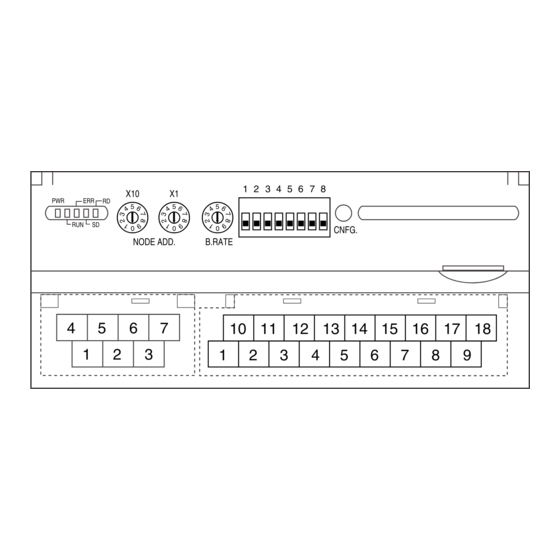
Page 2: Component Identification
Setting error or device Baud Rate Setting approx. 2 Hz error Error in the internal 5V Normal communication Received data error Data transmitting Data receiving EM-7816 Rev.4 P. 2 / 20 MG CO., LTD. www.mgco.jp 5-2-55 Minamitsumori, Nishinari-ku, Osaka 557-0063 JAPAN... - Page 3 4. DA − DI8+ Discrete Input 8 DI7+ Discrete Input 7 5. DG − 6. U(+) Power input (+) 7. V(−) Power input (−) EM-7816 Rev.4 P. 3 / 20 MG CO., LTD. www.mgco.jp 5-2-55 Minamitsumori, Nishinari-ku, Osaka 557-0063 JAPAN...
-
Page 4: Terminal Connections
EXTENSION MODULE 17 (.66) 11.5 65 (2.56) 54 (2.13) (.45) DIN RAIL 35mm wide 30 (1.18) [5 (.20)] 6 (.24) 10–M3 SCREW TERMINALS Discrete Input EM-7816 Rev.4 P. 4 / 20 MG CO., LTD. www.mgco.jp 5-2-55 Minamitsumori, Nishinari-ku, Osaka 557-0063 JAPAN... - Page 5 Di2+ DI2+ Di3+ DI3+ Di4+ DISCRETE 2ch. CURRENT INPUT INPUT DI4+ l EXTENSION MODULE EXTENSION MODULE DI2+ DI4+ DI6+ DI8+ DI1+ DI3+ DI5+ DI7+ EM-7816 Rev.4 P. 5 / 20 MG CO., LTD. www.mgco.jp 5-2-55 Minamitsumori, Nishinari-ku, Osaka 557-0063 JAPAN...
-
Page 6: Communication Cable Connections
The terminator must be connected across DA and DB. The Host PC can be located other than at the extreme ends of transmission line. EM-7816 Rev.4 P. 6 / 20 MG CO., LTD. www.mgco.jp 5-2-55 Minamitsumori, Nishinari-ku, Osaka 557-0063 JAPAN... -
Page 7: Wiring Instructions
R7MWTU WIRING INSTRUCTIONS EXTENSION MODULE ■ SCREW TERMINAL A ‘basic’ module (Model: R7MWTU-221-AD4) can be at- tached with one ‘extension’ module. The extension module Torque: 0.5 N·m is powered from the basic module. By combining two modules, single station can handle mixed ■... -
Page 8: Modbus - Basics
It is recommended to wait for a time period indicated under ‘recommended time out value’ in the above table to receive a response for a command. If no response is received for these time periods, take appropriate error processing such as retrying. EM-7816 Rev.4 P. 8 / 20 MG CO., LTD. www.mgco.jp 5-2-55 Minamitsumori, Nishinari-ku, Osaka 557-0063 JAPAN... -
Page 9: Modbus - Operations
Resetting energy count for Circuit 2. Same as with the address 5330. 5339 Loop test (Circuit 2) Turning Circuit 2 to the loop test mode. Same as the address 5336. (*) Factory setting EM-7816 Rev.4 P. 9 / 20 MG CO., LTD. www.mgco.jp 5-2-55 Minamitsumori, Nishinari-ku, Osaka 557-0063 JAPAN... -
Page 10: Modbus - Setting
CT sensor type (Circuit 2) Same as with the address 5603. 5612 Low-end cutout, Current (Circuit 2) %/10 Same as with the address 5608. (*) Factory setting EM-7816 Rev.4 P. 10 / 20 MG CO., LTD. www.mgco.jp 5-2-55 Minamitsumori, Nishinari-ku, Osaka 557-0063 JAPAN... -
Page 11: Modbus-Ascii
S = S1 + S2 + S3 (*) Factory setting Note: ‘1,’ ‘2,’ ‘3’ in expressions like Q1, Q2, Q3 indicate ‘R,’ ‘S,’ ‘T’ respectively. EM-7816 Rev.4 P. 11 / 20 MG CO., LTD. www.mgco.jp 5-2-55 Minamitsumori, Nishinari-ku, Osaka 557-0063 JAPAN... - Page 12 Phase angle between Phase 1 – 2 voltages ° 4085 UT23 Phase angle between Phase 2 – 3 voltages ° 4087 UT31 Phase angle between Phase 3 – 1 voltages ° EM-7816 Rev.4 P. 12 / 20 MG CO., LTD. www.mgco.jp 5-2-55 Minamitsumori, Nishinari-ku, Osaka 557-0063 JAPAN...
- Page 13 Reactive energy fraction, low tariff, outgoing kvarh/(10×2 4249 L-EPA_L Active energy fraction, low tariff, (incoming – outgoing) kWh/(10×2 4251 L-EQA_L Reactive energy fraction, low tariff, (incoming + outgoing) kvarh/(10×2 EM-7816 Rev.4 P. 13 / 20 MG CO., LTD. www.mgco.jp 5-2-55 Minamitsumori, Nishinari-ku, Osaka 557-0063 JAPAN...
- Page 14 P AVG 4 Active power AVG, History 4 4579 Q AVG 4 Reactive power AVG, History 4 4581 S AVG 4 Apparent power AVG, History 4 EM-7816 Rev.4 P. 14 / 20 MG CO., LTD. www.mgco.jp 5-2-55 Minamitsumori, Nishinari-ku, Osaka 557-0063 JAPAN...
- Page 15 Delta voltage MIN, 1 – 2 V/100 2971 U23 MIN Delta voltage MIN, 2 – 3 V/100 2973 U31 MIN Delta voltage MIN, 3 – 1 V/100 EM-7816 Rev.4 P. 15 / 20 MG CO., LTD. www.mgco.jp 5-2-55 Minamitsumori, Nishinari-ku, Osaka 557-0063 JAPAN...
-
Page 16: Total Harmonic Distortion (Thd)
1297 8297 THD U2N Phase voltage total harmonic distortion, Phase 2 %/10 1299 8299 THD U3N Phase voltage total harmonic distortion, Phase 3 %/10 EM-7816 Rev.4 P. 16 / 20 MG CO., LTD. www.mgco.jp 5-2-55 Minamitsumori, Nishinari-ku, Osaka 557-0063 JAPAN... - Page 17 2078 9078 HD U2N 31 31st 2113 9113 HD U3N 2 Phase voltage harmonic, Phase 3, 2nd %/10 2142 9142 HD U3N 31 31st EM-7816 Rev.4 P. 17 / 20 MG CO., LTD. www.mgco.jp 5-2-55 Minamitsumori, Nishinari-ku, Osaka 557-0063 JAPAN...
- Page 18 Pulse train input at Discrete input 8 is counted. The counter resets to 0 when a pulse is added at 999 999 999 counts. EM-7816 Rev.4 P. 18 / 20 MG CO., LTD. www.mgco.jp 5-2-55 Minamitsumori, Nishinari-ku, Osaka 557-0063 JAPAN...
-
Page 19: Device Status
‘1’ is placed when the respective errors are detected. All measuring operations stop while one or more system errors are detected. ■ DIAGNOSTICS ADDR. WORD PARAMETER UNIT 9217 Processing delays times 9219 Processing delay sequence number EM-7816 Rev.4 P. 19 / 20 MG CO., LTD. www.mgco.jp 5-2-55 Minamitsumori, Nishinari-ku, Osaka 557-0063 JAPAN... -
Page 20: Device Information
0100H : CC-Link 2000H : Modbus/TCP This register is read as follows depending upon model numbers. R7LWTU : 0090H (144) R7CWTU : 0110H (272) R7MWTU : 0012H (18) R7EWTU : 2010H (8208) 9627 Number of circuits 1 : 1 circuit (R7xWTU-211-AD4)
Need help?
Do you have a question about the R7MWTU and is the answer not in the manual?
Questions and answers