KVH Industries TracVision Master Quick Start Manual
Hide thumbs
Also See for TracVision Master:
- User manual (94 pages) ,
- Quick start manual (2 pages) ,
- User manual (2 pages)
Advertisement
Quick Links
TracVision
Quick Start Guide
The following instructions explain how to install and operate the Master Receiver Selector for
use with TracVision systems.
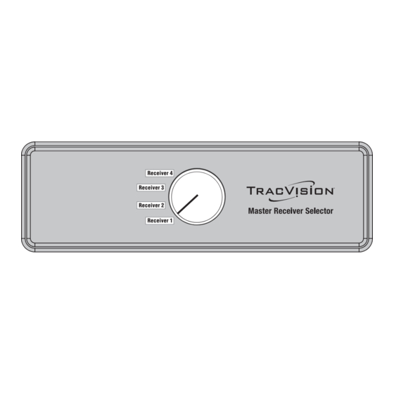
Using the Master Receiver Selector
The KVH Master Receiver Selector makes it easy to change which receiver is the master. Simply
turn the knob to select which receiver is in charge of satellite selection! You can connect up to
four receivers, and quickly switch master control to any one of them. Using the master receiver,
you can select among any of the channels carried by any of the satellites available to the system
for your satellite TV service.
Tip for DISH Network® Subscribers: For your convenience, KVH provides a listing of DISH
Network's HD programming and the satellite on which each channel is located. Visit www.kvh.com/
dishhd.
Technical Support
You can find a certified technician near you by visiting our website at
www.kvh.com/wheretogetservice.
If you need help finding a certified technician, please contact KVH
Technical Support:
Phone: +1 401 847-3327
E-mail: techs@kvh.com
(Mon.-Fri., 9 am-6 pm ET)
(Sat., 9 am-2 pm ET)
KVH, TracVision, and the unique light-colored dome with dark contrasting baseplate are registered trademarks of KVH Industries, Inc.
All other trademarks are property of their respective companies. The information in this document is subject to change without notice.
No company shall be liable for errors contained herein. © 2009-2010 KVH Industries, Inc., All rights reserved.
Master Receiver Selector
®
Receiver 4
Receiver 3
Receiver 2
Receiver 1
54-0646 Rev. B
1
Advertisement

Related Manuals for KVH Industries TracVision Master

Summary of Contents for KVH Industries TracVision Master
- Page 1 (Sat., 9 am-2 pm ET) KVH, TracVision, and the unique light-colored dome with dark contrasting baseplate are registered trademarks of KVH Industries, Inc. All other trademarks are property of their respective companies. The information in this document is subject to change without notice.
-
Page 2: Installation Instructions
Installation Instructions Wiring Diagram Reference For TracVision System Refer to IMPORTANT! TracVision M5/M7 Switchplate Unless the antenna is a TracVision M1DX/ Page 3 Configuration M3DX/R6DX, the Master Receiver Selector requires connections to the antenna’s RF1 TracVision M5/M7 Control Panel Page 4 and RF2 connectors. - Page 3 Wiring Diagram - TracVision M5/M7 Switchplate Configuration Antenna Data RF2 RF1 Grounding Block Power Switchplate +100-240 VAC Terminal Vessel Power Strip + – Power + – Power Master POWER Receiver Selector RECEIVER 1 RECEIVER 2 RECEIVER 3 RECEIVER 4 +12 VDC Receiver 1 Receiver 3 Vessel Power...
- Page 4 Wiring Diagram - TracVision M5/M7 Control Panel Configuration Antenna Data RF2 RF1 Grounding Block Power Switchplate +100-240 VAC Terminal Vessel Power Strip + – Power + – Power Master RJ 22 POWER Power Receiver Selector RECEIVER 1 RECEIVER 2 RECEIVER 3 RECEIVER 4 +12 VDC Receiver 1...
- Page 5 Wiring Diagram - TracVision M5/M7 GyroTrac Configuration Antenna RF2 RF1 Data Grounding Block Power +100-240 VAC Vessel Power +12 VDC Vessel Power Power ADCU Master POWER Receiver 60 59 48 47 Selector DB9 Maintenance Port RECEIVER 1 RECEIVER 2 RECEIVER 3 RECEIVER 4 13 14 25 26...
- Page 6 Wiring Diagram - TracVision M9 Antenna Data/ RF2 RF1 Power Grounding Output to Block Antenna OUTPUT TO ANTENNA MAINTENANCE PORT RF PORT POWER IN Power In +100-240 VAC Vessel Power +24 VDC Vessel Power Power Master POWER Receiver Selector RECEIVER 1 RECEIVER 2 RECEIVER 3 RECEIVER 4...
- Page 7 Wiring Diagram - TracVision M1DX/M3DX/R6DX Input Antenna Destacker, Single-Output INPUT TO TV (KVH Part #19-0347, OUTPUT/TO RECEIVER Sold Separately) Power/ Output/ Data To Receiver Multi-service +100-240 VAC Interface Box To KVH Antenna Vehicle/Vessel Power POWER (10-16VDC) TO KVH 110W/HD UNSTACKED STACKED MAINTENANCE PORTS ANTENNA...
- Page 8 Wiring Diagram - R5SL/R4SL/R5/R4/C3 Antenna RF2 RF1 Power/Data Grounding Block +100-240 VAC Switchplate Vehicle/Vessel Power Power Master POWER Receiver Selector RECEIVER 1 RECEIVER 2 RECEIVER 3 RECEIVER 4 Receiver 1 Receiver 3 Receiver 2 Receiver 4 +100-240 VAC To Vehicle/Vessel Satellite In AC Power Receiver 4...
- Page 9 Wiring Diagram - 2 Master Receiver Selectors (6 Master Receivers) To make receivers 3, 4, 5, or 6 the master receiver, set the knob on this Master Receiver to the Receiver 4 position first. +100-240 VAC To Antenna Then use the knob on the other Master Receiver Selector to Vehicle/Vessel Master choose the master receiver.
- Page 10 Wiring Diagram - 1 Master Receiver Selector and Multiswitch (2 Master Receivers with Multiple Slaves) To Antenna +100-240 VAC Vehicle/Vessel Master Power Receiver Selector Power POWER RECEIVER 1 RECEIVER 2 RECEIVER 3 RECEIVER 4 Receiver 1 Receiver 3 Power Receiver 2 Receiver 4 Supply Multiswitch...
Need help?
Do you have a question about the TracVision Master and is the answer not in the manual?
Questions and answers