Table of Contents
Advertisement
Quick Links
Advertisement
Table of Contents

Subscribe to Our Youtube Channel
Related Manuals for Santec PEM-340


Summary of Contents for Santec PEM-340
- Page 1 Polarization Extinction Ratio Meter PEM-340 Operation Manual...
- Page 2 1) When this product is brought out of Japan, some laws or regulations of a destination country may prohibit this product from being used there. In such countries, the use of this product may lead to punishment. Please note, that in such cases Santec Corporation shall not be held responsible in anyway.
- Page 3 Polarization Extinction Ratio Meter PEM-340 About This Manual This manual explains the operation and safety features of the PEM-340 Polarization Extinction Ratio Meter. To ensure the safe operation of the instrument, and to prevent the risk of personal injury and/or damage to the equipment we recommend that you read the manual fully before commencing installation and operation.
-
Page 4: Table Of Contents
PEM-340 Operation Manual Contents About This Manual 1. Introduction 2. Product Composition 3. Specifications 4. Features 4-1. Real Time Display 4-2. Offset Cancel 4-3. Communication Interfaces 4-4. Analog Data Output 4-5. Stopped Polarizer Function 4-6. High Speed Measurement 5. Principle of Operation 6. - Page 5 Polarization Extinction Ratio Meter PEM-340 8-3. Offset Cancel 8-4. Changing Display Units 8-5. PER Averaging Function 8-6. Setting GP-IB address and Delimiter 8-7. Setting Wavelength Range and Measurement Speed 8-8. Analogue Output 8-9. Changing the Optical Connector 9. Communication Interfaces 9-1.
- Page 6 PEM-340 Operation Manual...
-
Page 7: Introduction
The PEM-340 is easy to use, but to obtain the most from your unit we recommend that you read this manual fully and become familiar with its contents prior to operation. We hope that you will be... - Page 8 PEM-340 Operation Manual...
-
Page 9: Product Composition
Polarization Extinction Ratio Meter PEM-340 Product Composition PEM-340 Body (1) Power Key (1) Power Cord (1) AIF Exclusive Use Cable (1) Operation Manual Inspection report (1) - Page 10 PEM-340 Operation Manual...
-
Page 11: Specifications
Polarization Extinction Ratio Meter PEM-340 Specifications Normal power High power Category Unit Wavelength Range 1260-1630 PER Dynamic Range -5~+10dBm 0 to 50 -15~+10dBm -5~+20dBm 0 to 40 0 to 40 PER Range -15~+20dBm -25~+10dBm 0 to 30 0 to 30 -35~+10dBm... - Page 12 PEM-340 Operation Manual...
-
Page 13: Features
4-3. Communication Interfaces The PEM-340 can be used as a stand alone bench-top type measurement instrument. However, it also boasts industry standard GPIB and RS-232C interfaces through which the unit can be fully controlled and through which all parameters can be monitored. The PEM-340 is thus suitable for automated measurements in production environments and for integration into fully automatic alignment systems. -
Page 14: Stopped Polarizer Function
4-6. High Speed Measurement To provide additional flexibility the PEM-340 can operate at one of three measurement speeds. The default 2.5Hz measurement speed is recommended as it provides the highest dynamic range for both PER and optical power. -
Page 15: Principle Of Operation
Polarization Extinction Ratio Meter PEM-340 Principle of Operation The above diagram shows the design of the PEM-340 unit. The optical fiber is connected through the input connector. The light from the fiber is then collimated by a lens, and after passing through a rotating polarizer is incident on the photodetector. - Page 16 The PEM-340 displays a polarization angle of zero when the polarization axis is vertical and aligned with the alignment notch of the input connector.
-
Page 17: Panel Descriptions
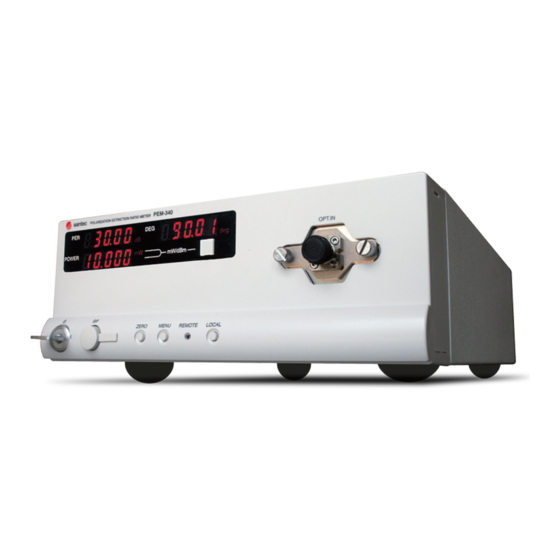
Polarization Extinction Ratio Meter PEM-340 Panel Descriptions 6-1. Front Panel (12) (11) (10) (1) PER Display Panel Displays the value for polarization extinction ratio (PER) in dB. (2) Optical Power Display Panel Displays the optical power. The measurement unit can be set to either mW or dBm and is toggled by pressing the Optical Power Unit Selector Key (5). - Page 18 The optical input connector is FC / SC conversion type. Connection of the optical fiber with dust and dirt on the end of the optical connector of PEM-340 cause loss of optical input, therefore, please clean the connector periodically.
- Page 19 Pressing this key when the power to the PEM-340 is first switched on sets the RS-232C delimiter to LF (line feed). (11) Serial Interface (SIF) Connector Used for RS-232C communication.
-
Page 20: Rear Panel
PEM-340 Operation Manual 6-2. Rear Panel (1) Analogue Interface (AIF) Connector Provides analogue output of PER, Optical Power and Polarization Angle. (2) Mains Connector Socket (3) Fuse Housing (4) Slit for Heat dissipation There is a cooling fan inside at this location. Please do not cover the slit. -
Page 21: Installation
Polarization Extinction Ratio Meter PEM-340 Installation 7-1. Operating Environments Pay attention to the following guidelines for safe, trouble-free operation. This product is a high-precision device. • Do not place in direct sunlight. • Do not place under high temperature and high humidity. - Page 22 PEM-340 Operation Manual...
-
Page 23: Operation Procedures
Polarization Extinction Ratio Meter PEM-340 Operation Procedures 8-1. Power On / Off The power cord socket is located on the unit’s rear panel. Check that the local mains voltage is within the specification, and plug the power cord into the socket. Connecting an incorrect voltage will cause damage to the unit. - Page 24 232C delimiter. In this example the delimiter is CR. It is recommended to wait at least five minutes to allow the PEM-340 unit to warm up, and to compensate for the dark current in the photodetector, before measurements are taken. The procedure to compensate for the photodetector dark current is described in Section 8-3.
-
Page 25: Optical Fiber Connection
Before connecting the input light, check that the optical power does not exceed the maximum specified level for the PEM-340. The maximum level of the standard model PEM-340 is +10dBm. If the optical input exceeds this limit, there is a risk of damage to the units's internal optical elements. -
Page 26: Offset Cancel
The Offset Cancel function enables compensation of the dark current of the photodetector. The PEM-340 can be used directly after the power has been switched on and the initialization procedure has completed. However, to ensure high accuracy, it is recommended that the unit is allowed at least five minutes to warm up before any measurements are taken. -
Page 27: Setting Gp-Ib Address And Delimiter
8-6. Setting GP-IB address and Delimiter The PEM-340 stores the GPIB address and delimiter settings in the internal memory. After changing the settings, the settings will be stored in the memory and the data will be kept, even if power is lost. -
Page 28: Setting Wavelength Range And Measurement Speed
PEM-340 Operation Manual 8-7 . Setting Wavelength Range and Measurement Speed The PEM-340 can change and store the wavelength range and the measurement speed. Press the [MENU] key once. The display will show the measurement speed setting. Switch the setting display between measurement speed and measurement wavelength by pressing the [MENU] key again. -
Page 29: Analogue Output
Polarization Extinction Ratio Meter PEM-340 8-8. Analog Output The analog interface (AIF) located on the rear panel of the PEM-340 enables the measured signals to be monitored as analogue voltages. The voltages mirror directly the values displayed on the front panel with the same refresh rate. The connector is a Hirose Electric HR10-7R- 6S. -
Page 30: Changing The Optical Connector
4. Ensure the connector socket is correctly seated and flat with the face of the PEM-340 unit. Replace the two fixing screws and tighten finger tight. Do not overtighten the screws as this may cause damage to the unit. - Page 31 Polarization Extinction Ratio Meter PEM-340 How to clean the optical input connector Please clean the connector using a cleaner for LC connector (φ1.5mm or less) such as the following photo. Stick type NEOCLEAN S125 Caution of using bare fiber adapter Please read the following for trouble-free operation.
- Page 32 PEM-340 Operation Manual 8-10...
-
Page 33: Communication Interfaces
Polarization Extinction Ratio Meter PEM-340 Communication Interfaces The PEM-340 supports both GPIB and RS-232C communication protocols. This enables remote operation of the device and integration in automated test and measurement systems. Although the two protocols are fundamentally different the core control commands are the same. -
Page 34: Gpib Function
The PEM-340 provides support for RS-232C communication through the SIF connector on the front panel. The RTDX (transmit) terminal of the PEM-340 should be connected to the receive terminal of the external device (e.g. computer). The RRDX (receive) terminal of the PEM- 340 should be connected to the transmit terminal of the external device. -
Page 35: Control Commands
On’ procedure; for details see Section 8-1 Power On. To read data from the PEM-340 it is first necessary to set the output parameter to the required data parameter. When subsequent read commands are issued, the data corresponding to the set parameter is read. - Page 36 PEM-340 Operation Manual Command Description Sample Offset cancel Reads out PER(dB) Reads out optical power in dBm Reads out optical power in mW Reads out Output angle(deg) Reads out data 1 Read out measurement speed Sets measurement speed 2.5Hz RFd 3...
- Page 37 Polarization Extinction Ratio Meter PEM-340 Status Command The SU command is provided to enable the current status of the rotating polarizer and the measurement speed setting to be probed. The command returns a six digit number. The interpretation of the six digit number is detailed below: 1st digit –...
- Page 38 PEM-340 Operation Manual 9-4. Sample Programs Sample program written by Microsoft Visual Basic Ver6.0. ■ 9-4-1 GP-IB sample program Private Const BDIndx = 0 ' GP-IB board number Private Const pad = 1 ' Primary GP-IB address Private Const sad = 0...
- Page 39 Polarization Extinction Ratio Meter PEM-340 ■ 9-4-2 RS-232C sample program Private Sub MSComm1_Init() ' <RS-232C port initialize routine> MSComm1. CommPort = 1 ' Select RS-232C port 1 as communication port MSComm1. Settings = " 9600, n, 8,1" ' set 9600bps, 8bit, np, s1 MSComm1.
- Page 40 PEM-340 Operation Manual...
-
Page 41: Care And Maintenance
Care and Maintenance 10-1. Care The PEM-340 is a precision optical instrument and as such requires reasonable care to be taken with its handling, operation and storage. In particular: • Do not drop or expose the unit to shock as this may cause misalignment of the optics, •... - Page 42 PEM-340 Operation Manual 10-2...
-
Page 43: Re-Packing And Shipping
Polarization Extinction Ratio Meter PEM-340 Re-packing and shipping Special attention for re-packing and shipping is required when you ship the instrument for repair or to a remote location. 11-1. Re-packing Please make sure that the original shipping box is used during the shipment, according to the following instructions. - Page 44 PEM-340 Operation Manual 11-2...
-
Page 45: Troubleshooting
Cable is not connected properly. Check the connection of the cable. possible. Check the pin assignment of the Cable is not wired correctly. cable. If the unit is still not operating correctly after checking the above, please contact Santec's technical support division. 12-1... - Page 46 PEM-340 Operation Manual 12-2...
-
Page 47: Warranty
In no event shall Santec Corporation of Japan nor any subsidiary of Santec nor any distributor of Santec’s products be liable to the customer for any damages, including lost profits, or other incidental or consequential damages arising out of the use or inability to use this product. - Page 48 SANTEC EUROPE LIMITED Tel: +44-20-3176-1550 11F Room E, Hua Du Bldg., No.838 Zhangyang Road, Pudong, Shanghai 200122 China SANTEC (SHANGHAI) Co., Ltd Tel: +86-21-58361261, +86-21-58361262 Fax: +86-21-58361263 www.santec.com E-Mail: info@santec.com PEM-340-M-E-v1.1 / CODE-201811-HS-KW-CPY / Santec corporation /AD&Design sec. 13-2...
Need help?
Do you have a question about the PEM-340 and is the answer not in the manual?
Questions and answers